How to tackle fast recovery from radio link failure
Principal Researcher, Radio network solutions
Master Researcher, Networks
Principal Researcher, Radio network solutions
Master Researcher, Networks
Principal Researcher, Radio network solutions
Master Researcher, Networks
Rel-15 saw the introduction of several Dual Connectivity (DC) options including New Radio (NR) access. In DC, the user equipment (UE) is connected simultaneously to a Master Node (MN) and a Secondary Node (SN). The UE can be configured to operate in carrier aggregation (CA) with each node. The cells of the MN where the UE is operating in CA are referred to as the master cell group (MCG), while those of the SN are referred to as the secondary cell group (SCG).
The fast MCG link recovery feature introduced later in Rel-16 aims to decrease the connection interruption time during radio link failure (RLF). By utilizing the SCG connectivity, the interruption time caused by MCG RLF can be reduced from several seconds down to a typical handover interruption time of 30 -70ms. For end users, this directly translates into decreased service interruption times.
The different DC options available since Rel-15 are collectively referred to as Multi-Radio Dual Connectivity (MR-DC), and can be one of these (see Figure 1):
- EN-DC: the MN is an LTE, or E-UTRA, node and the SN is an NR node. The UE is connected to the 4G Evolved Packet Core (EPC). This option was introduced in the early drop of Rel-15 as a first step towards 5G deployments.
- NGEN-DC: same as EN-DC, but the UE is connected to the 5G Core (5GC)
- NE-DC: the MN is an NR node and the SN is a E-UTRA node. The UE is connected to 5GC
- NR-DC: both the MN and the SN are NR nodes and the UE is connected to the 5GC
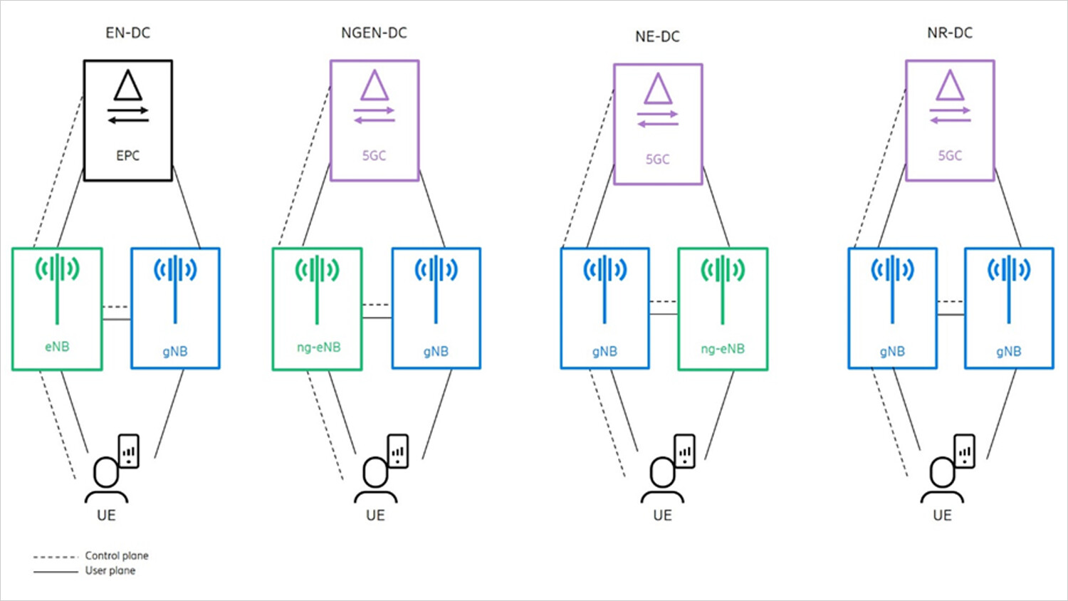
Figure 1 MR-DC options
To improve signaling robustness, in all MR-DC options, the UE may be configured with a split Signaling Radio Bearer (SRB), which enables transmission of Radio Resource Control (RRC) signaling via the MCG and/or SCG. That is, E-UTRA or NR RRC messages such as RRC Reconfiguration can be sent using the MN and/or SN radio resources. Additionally, in EN-DC, NGEN-DC and NR-DC, the UE may be configured with SRB3, which is an SRB terminated in the SN and used only for control signaling between the SN and UE (meaning where no coordination with the MN is required). Split SRB and SRB3 are illustrated in Figure 2.
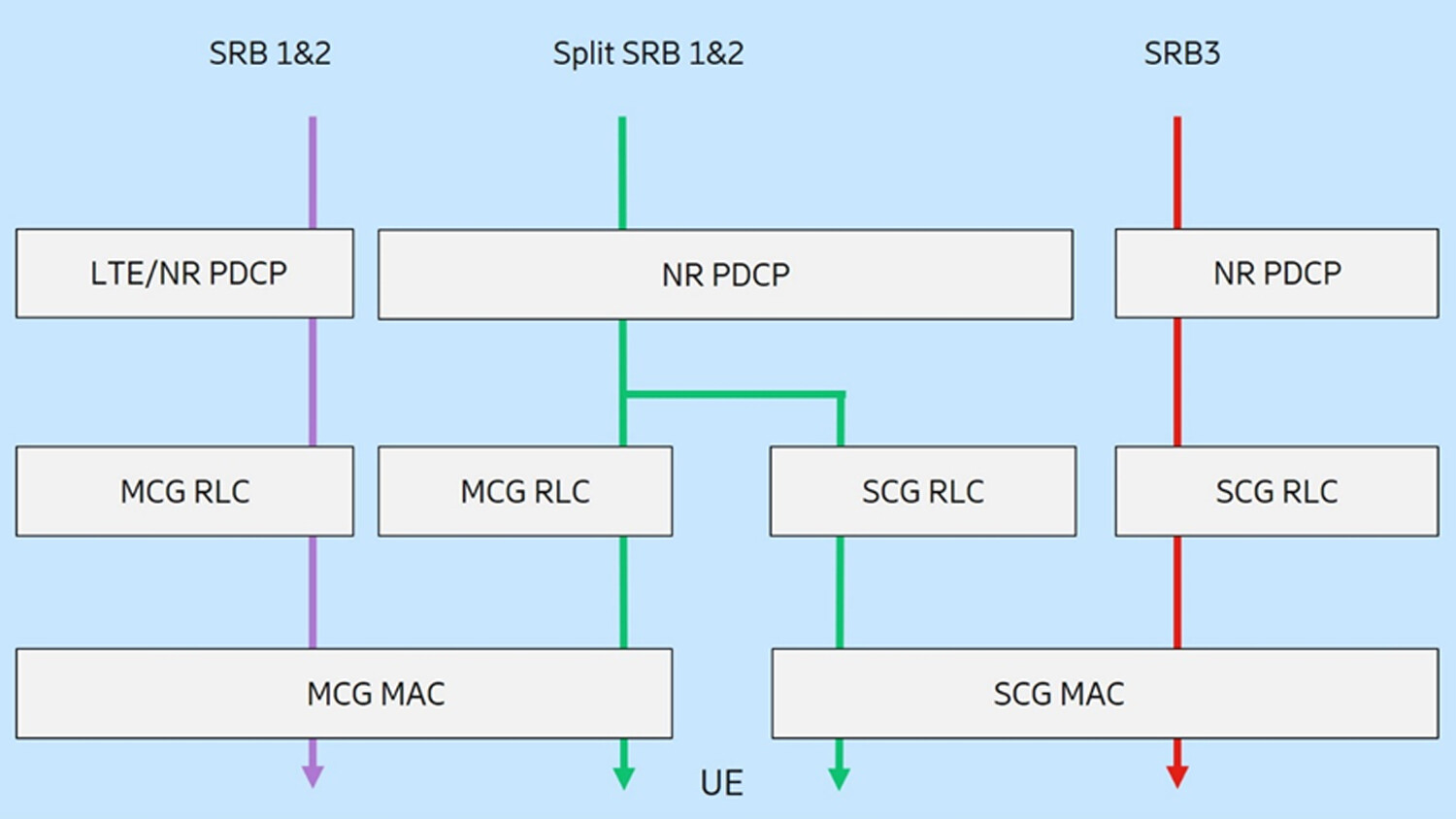
Figure 2 MR-DC SRB options
In NR or LTE standalone operation, a UE detecting loss of downlink synchronization (physical layer problem), maximum random access attempts (random access problem) or maximum number of RLC retransmissions will declare RLF and trigger the RRC re-establishment procedure. Details about this can be found in the 3GPP documents TS 36.331 and TS 38.331.
This procedure involves suspending all current transmissions, scanning for the best neighboring cell on the same or neighboring frequency (cell reselection) and triggering the RRC re-establishment procedure in the detected best cell. In total, this causes an outage lasting typically a few seconds before the UE is resynchronized again with the network, connectivity is restored, and data transmission is resumed.
In LTE-DC, if the UE encounters a failure towards the SCG, it does not trigger the re-establishment procedure, as the connection to the MN could be working perfectly. The feature builds on the principle that as long as there is connectivity between the network and the UE, in this case via the MCG, it is best to maintain the network control over how the situation is resolved. So, the UE initiates an SCG failure recovery procedure, also referred to as SCG Failure Information, where the UE sends a report to the MN indicating that the SCG has failed, the reason for the failure and any available measurements. The MN can then use this information to release, reconfigure or change the SN.
The SCG failure recovery procedure was adopted in Rel-15 for all MR-DC options. However, in Rel-15, problems in the MCG still lead to the UE triggering the re-establishment procedure, even when the SCG is still working. This is unnecessary, as there is still connectivity between the SN and the UE. Following the same principle of network control as applied for the SCG failure information procedure, we at Ericsson have, since early Rel-15 discussions, been driving the introduction of fast MCG link recovery, see for example, R2-1702711 and R2-1901413, to improve robustness against RLF in MR-DC. This was not agreed for Rel-15, but for Rel-16, a work item on CA&DC enhancements was agreed, in which network-controlled recovery from MCG failure is one of the objectives.
Further motivation for introducing a fast MCG link recovery procedure is given by the multiple deployments that are enabled when using different ranges of frequencies (from 700 MHz up to 52.6 GHz) over the MCG and SCG. This means that when the frequency deployed in the MCG is higher than the one deployed in the SCG, the probability of problems in the MCG increases, while the SCG may be more stable.
Fast MCG link recovery is supported for UEs in MR-DC configured with either split SRB or SRB3. A prerequisite for the fast MCG link recovery is that the SCG is not suspended, so that it can be used for the MCG failure reporting.
A UE in MR-DC does not trigger RRC re-establishment upon detecting an RLF. Instead, it suspends the MCG transmissions of all bearers and prepares an MCGFailureInformation message, containing the reason for failure and any available measurements at the time of failure, in order to help the network take the appropriate action. The UE then sends the MCGFailureInformation message to the network via the SCG, using the SCG radio resources either in split SRB1 or SRB3. If both split SRB1 and SRB3 are configured, the UE sends the message via split SRB1. In case the message is sent via SRB3, instead, the SN will forward the MCGFailureInformation message to the MN via internode interface between the MN and SN.
Upon receiving the MCGFailureInformation message from the UE, the MN determines the best action to address the MCG failure based on, for example, the measurement information received from the UE. The action may typically be a reconfiguration to change the Primary Cell of the UE to a better cell to restore the MCG connectivity.
Alternatively, if no suitable target cell is determined, the network may send an RRC release message to the UE to release the connection. In case split SRB1 is used, the network response is directly sent to the UE, by using the SCG leg of the split SRB – see figure 3. For the SRB3 case, the MN sends the response message to the SN, which then encapsulates it inside an SN RRC message and sends it to the UE.

Figure 3 MCG failure handling via split SRB1
The main benefit of the MCG failure recovery procedure is that the rather long interruption during MCG RLF detection and subsequent cell reselection and RRC re-establishment can be avoided. Depending on the UE configuration, carrier frequency and network deployment, this can take up to seconds. Instead, UE connectivity can be maintained via the SCG during the time the MCG is restored and typically only a short interruption – comparable to a normal handover interruption (30-70ms) – is experienced, while the network prepares and sends the proper response message to reconfigure the UE. Note that this is the physical layer interruption and that the IP level interruption may be longer, depending on the link layer protocols; PDCP, RLC and MAC.
In contrast to the UE controlled RRC re-establishment procedure, the network remains in control during MCG failure recovery, as long as SCG connectivity is still there. The network can select the most appropriate action/reconfiguration, based on UE provided measurement information as well as considering the network’s overall situation like network load, subscription and service information (for example QoS of active bearers of the UE).
Learn more
Recap on our previous blog post, LTE-NR tight interworking and the first steps to 5G.
Read our blog post on 3GPP technologies in unlicensed spectrum: A contributor to the common good.
Dive into our Ericsson Technology Review article on the 5G New Radio evolution.