Meet the 5G racers! Testing 5G latency on a RC hobby racetrack
What performance can we expect from a regular 5G network deployment today? There are many ways 5G capabilities can be put to the test. But for our experiment, we picked an extreme scenario based on the following question:
How close can we match the performance of the radio-controlled (RC) hobby car with low-cost, off-the-self, do-it-yourself (DIY) electronics components and production 5G technology?
Start your engines: RC hobby vs. 5G hobby and drone
RC hobby products are purpose-built for the one thing: low-latency control and first-person-view (FPV) video for local operation. 5G, in contrast, is a multi-purpose technology for nationwide deployments. RC racing is a worthy challenger of 5G's flexibility.
For this experiment we used low-cost popular DIY components, and our commercial 5G products to show the developer community what is already possible with today’s 5G technology.
To assess 5G’s “racing” performance we have two benchmarks. First, we draw on human reaction time studies including experience from online multi-player gaming. Second, we have measured the actual performance of typical RC hobby radios to set up a comparative benchmark.
How to understand latency and human reaction time
Unless you are a fighter pilot or formula 1 driver, human reaction time is typically around 200-250 milliseconds (ms). This is the time it takes to make a conscious reaction to a visual trigger. This is typically tested by displaying a figure on a display and measuring the time it takes for the test subject to press a button when a shape appears. This time difference is recorded as the reaction time. You can test this yourself here.
Other studies show that the fastest a human can process and understand visual information is around 15ms. That is, visual information that is displayed for at least 15ms will be perceived by the human brain. To put it another way, receiving visual information at a faster rate than this will not be captured by the human brain.
Drawing on the experience of online gaming, latency up to 15ms is practically instantaneous for humans, however increasing latency above 15ms will gradually impact human performance negatively. When latency reaches somewhere between 75-100ms, the lag will be consciously perceived, and people will have to anticipate events instead of reacting to the received information. While this is one way to cope with constant lag up to a limit, when the latency becomes variable i.e., there is a high jitter, the human performance will be severely impacted even at lower latencies.
From this we can summarize that latency below 15ms does not affect human performance, whereas anything above 100ms will begin to negatively impact the performance noticeably. Somewhere in between, say around 50ms is an ideal balance in terms of stressing technological limits and achieving close to optimal human performance in fast-paced real-time settings.
Latency and human reaction time in the RC hobby
There are two independent communication channels used in the RC hobby:
- One channel for controlling cars, drones, and other vehicles, by sending joystick position information from the radio controller to the receiver on the vehicle
- Another channel for streaming analog FPV video from the vehicle to a regular or head-mounted display

Figure 1: RC Control Loop
Stick-to-Output-Signal Latency (STOL) defines the time it takes to get a joystick movement on the radio controller to result in a control signal change on the remote receiver. For video, Glass-to-Glass Latency (GTGL) is the time it takes for an event happening in front of the camera to appear on the display at the remote end. The overall latency of the end-to-end system is the sum of STOL and GTGL. The lower the latency of these two channels the faster the pilot can react and change the trajectory of the vehicle.
We will see real numbers later but for now, let's assume both of these channels are in the order of 25ms, meaning the shortest time new control can be executed on the car or drone as a result of an event captured by the camera is 50ms. To put this into context, at the extreme speed of 130km/h or 80mph, which is the speed of some racing drones, 50ms translates to 1.79m or 5.9ft distance traveled before the reaction to an event can take effect. For more color, add that the dimensions of a drone racing gate can be as small as 5ft x 5ft. Low latency is important.
Of course, we cannot neglect the effect of the human in the loop when considering the total control latency. The typical human reaction time is around 200-250ms. Since racing requires fast reflexes, let's assume that skilled pilots have as low as 150ms reaction time. That gives us 200ms total of human reaction time plus control loop lag. This is the total time it takes to react to an event happening in front of the camera, a pilot taking conscious action, and the control signal changing on the drone. As a side note, this does not take into account the physical limitations of the vehicle i.e. additional delay because of the inertia of the system. In our example of 130km/h or 80mph, that translates to 7.2m or 23.6ft distance traveled. In practice, this means that pilots need to anticipate events and execute control moves before the visual trigger. To do so, pilots tune in their equipment and, with practice, "learn" the response characteristics of the entire system, including radio as well as the physical behavior of the vehicle. A key component to enable "learning" is the low variation of communication lag. Therefore, while low latency matters a lot, low jitter is probably just as important.
Building the 5G car
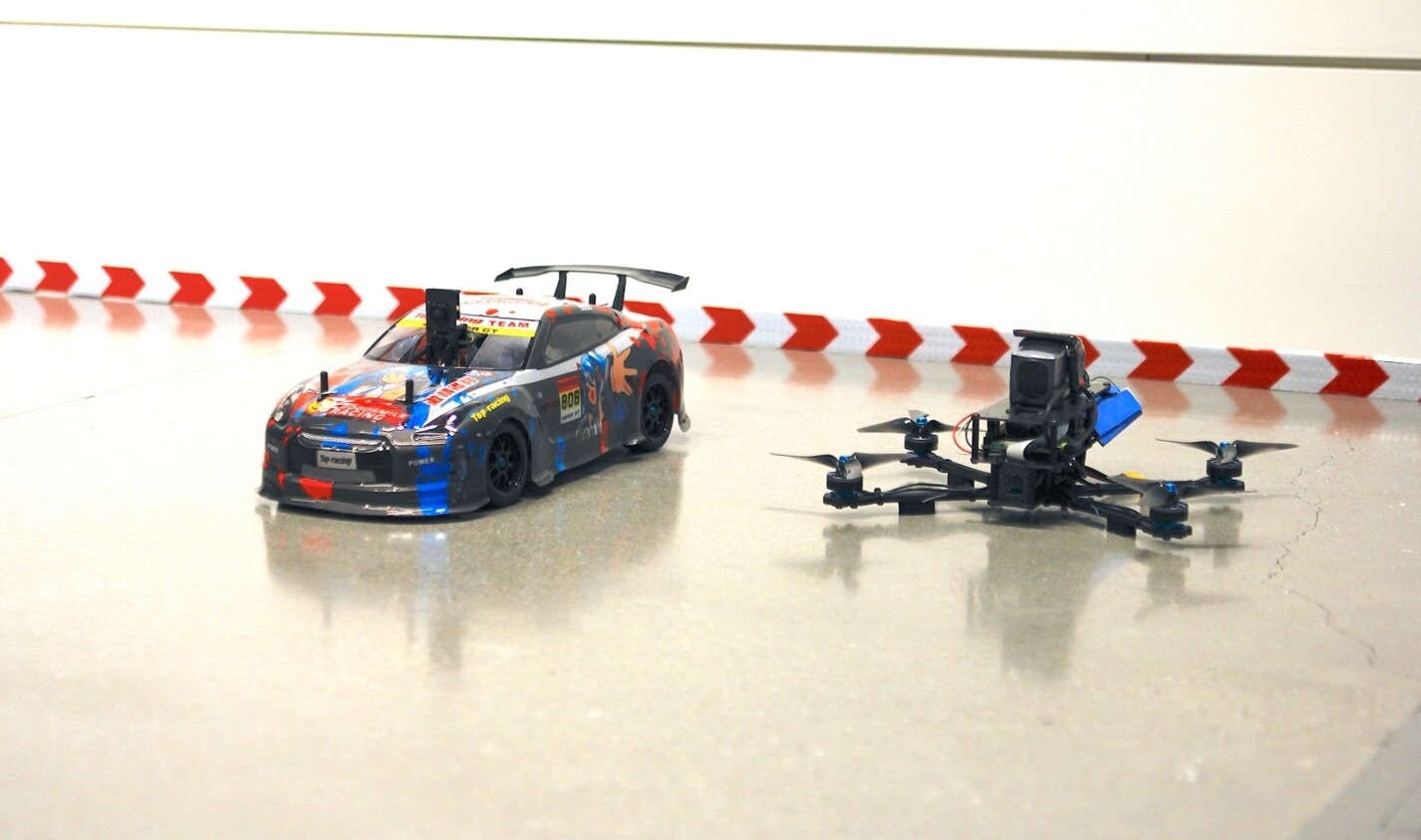
Figure 2: The 5G-powered RC hobby and drone
We used a 1/10 scale RC car kit as the basis of our 5G car and added a top deck for the onboard computer and 5G modem.
The main components of an RC car are shown below. There is the radio controller sending the steering and throttle signals to the receiver installed in the car. The receiver will send the control signals to the servo steering the car and the electronic speed controller (ESC) adjusting the motor's speed.
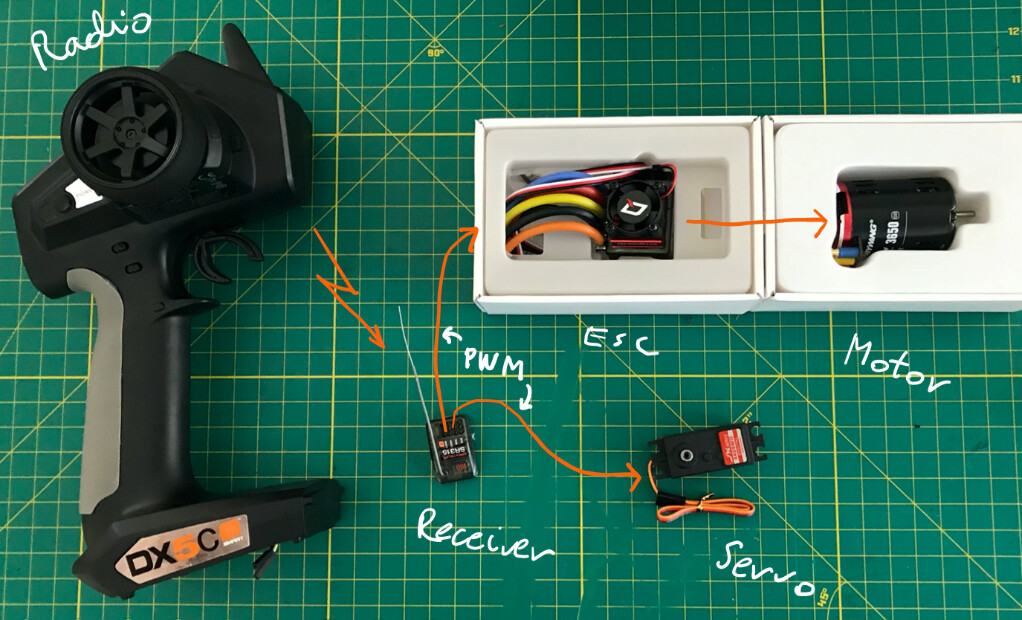
Figure 3: RC Car Components
The control signal is a kind of pulse-width modulation (PWM) signal. One main component of the control latency of the RC system is rooted in the PWM signal parameters. Traditionally, the RC hobby would use PWM signals with a 50ms framerate, meaning the PWM signal for the servo and ESC would be refreshed every 50ms or 20Hz. The actual signal that determines the position of the servo and the speed of the motor is much shorter, however. Typically, signal width can be anywhere between 1ms to 2ms with the neutral position being at 1.5ms. The PWM signal is depicted below.
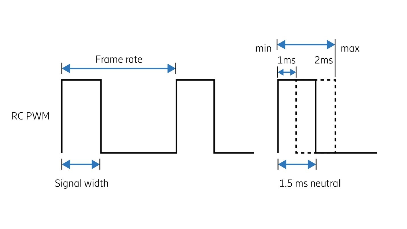
Figure 4: PWM Signal Overview
Over the years, the hobby has evolved, and the framerate has increased significantly. Depending on the proprietary protocol employed, 22ms/19ms and 11ms/9ms are commonly used framerates today. Some specialized products can even support as low as 5.5ms framerates. . Increasing the framerate does present some trade-offs, however. As it requires more frequent signal updates, it also consumes more radio resources. Because the radio channel's bandwidth is limited and coping with radio interference requires overhead , this results in a limited number of control channels between the radio controller and the receiver. In fact, when using 5.5ms framerates, only two control channels are available which is just enough for the two main controls of a car: steering and throttle. For our reference measurements, we will use the more common 11ms (about 90Hz) framerate.
To make a 5G car we had to add a few components. We used the popular Raspberry Pi 4 as the onboard computer. The board has fairly good CPU performance with 4 cores and the hardware-accelerated H.264 video encoding is handy for our FPV video streaming needs. We added a 5G modem with M.2 form factor attached to a USB adapter for connectivity. We used SimCom's 5G modules (www.simcom.com) for our project. This gave us a compact 5G control and communication module. Probably the first compact “dedicated” 5G control and communication unit ever assembled!
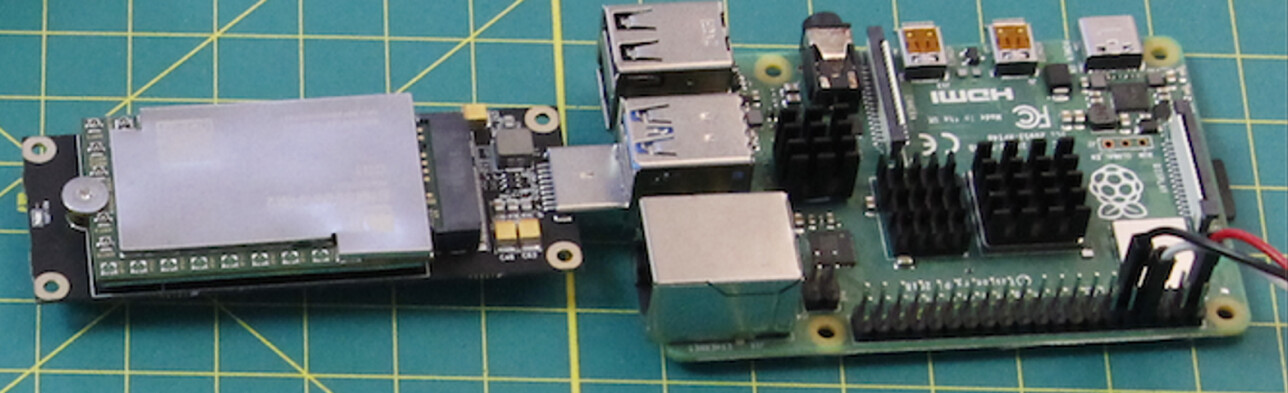
Figure 5: 5G Communication and Control Module
The Raspberry Pi needs 5V power, so we added a voltage converter that will derive 5V/3A from the main battery of the RC car. Although we could use the GPIO pins of the Raspberry Pi, in order to get a clean PWM signal we decided to use a dedicated servo controller connected via the USB port to generate PWM signals needed by the ESC and steering servo. This dedicated controller can also serve as a dead man switch in case of problems with the onboard computer. To integrate with RC control, we added a servo multiplexer that can switch whichever PWM input signal source is sent to the servo and ESC. We configured one button of the radio controller that selects when the Raspberry Pi signals are in control of the car and when the RC radio takes control.
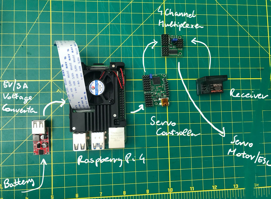
Figure 6: Adding Onboard Computer to the RC Car
The remote control of the 5G car is based on two Raspberry Pis. One is the controller with a USB joystick attached to it. We implemented a simple Python script to read the joystick positions periodically at a configurable rate and send the signals in Internet Protocol (IP) packets over the network. On the car, we have the onboard Raspberry Pi as the receiver that interprets the IP packets received and updates the servo controller with the appropriate position information. The servo controller in turn changes the PWM signals on its output pins. The communication between the controller and the receiver computers can take place over any IP network.
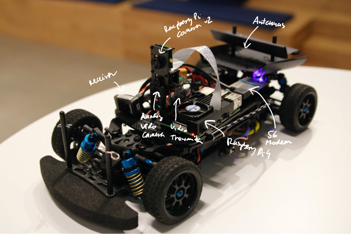
Figure 7: Interior of the 5G Car
Building the 5G drone
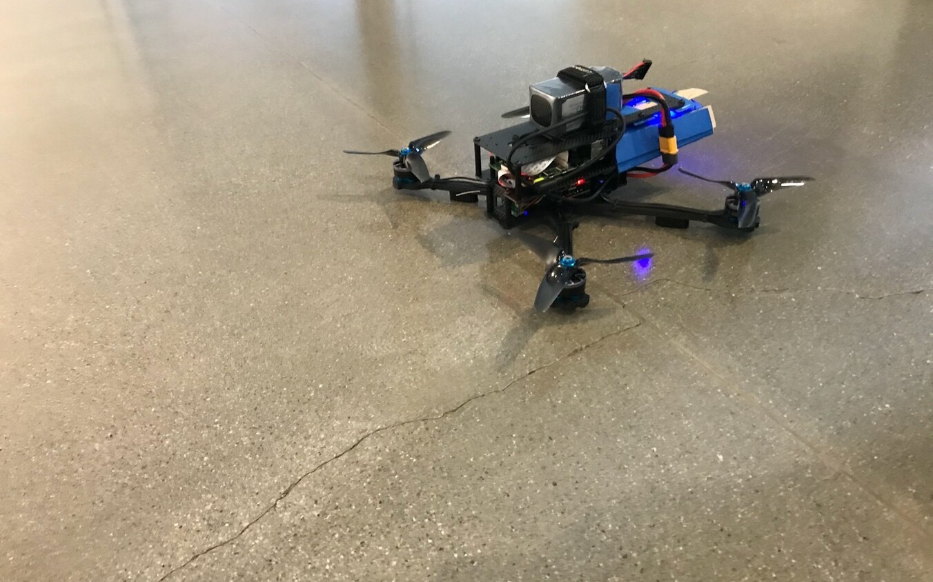
Figure 8: The 5G-powered drone
For the drone platform, we selected a racing drone kit with 7-inch arm length. This size is large enough to fit our onboard computer and 5G communication module and at the same time small enough to be suitable for indoor operation.
The main components of an RC drone are shown below. The RC radio is sending joystick commands to the receiver on the drone. The receiver in our build is using the popular SBUS protocol to send the control messages to the flight controller. The SBUS protocol is a simple serial protocol. It uses 25 bytes to transfer 18 channels at 100k baud rate. With all the overhead it takes 3ms to get one SBUS frame transmitted. In fact, there are pause periods and hence the actual framerate of the SBUS protocol is typically 9ms. The flight controller (FC) is processing the SBUS protocol, and depending on the flight mode selected, it can use its onboard sensors to assist the pilot with leveling and stabilizing the drone. The FC then sends individual motor control signals to the ESC, which in turn drives the motors. There is a separate radio transmitter for the analog PAL/NTSC video stream from the drone to the pilot’s display.
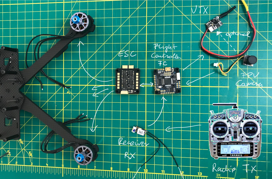
Figure 9: RC Drone Components
We replaced the upper carbon fiber plate of the drone kit with our own deck for the onboard computer and 5G modem. Similar to the car build, we used a Raspberry Pi 4 as an onboard computer. The components of the 5G drone are depicted below.
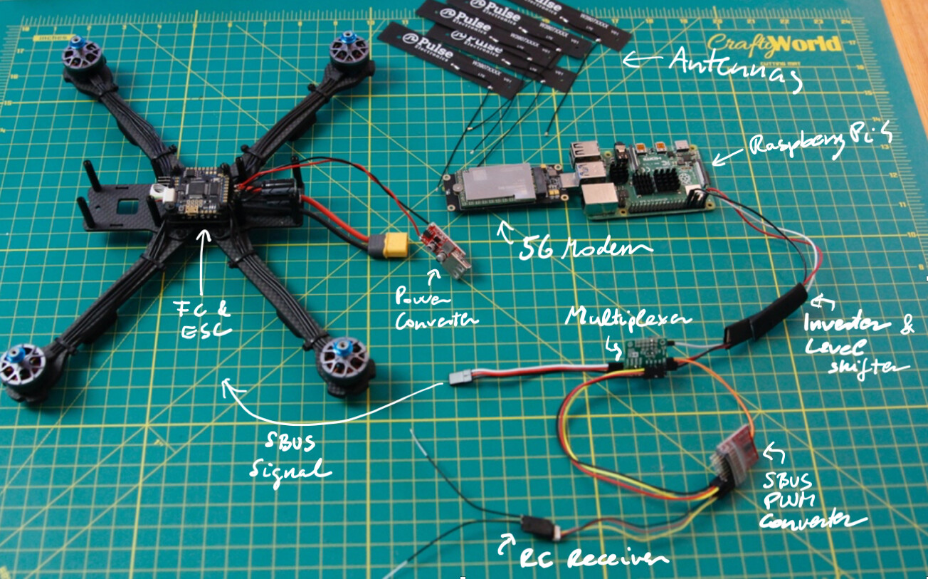
Figure 10: 5G Drone Components
The 5G network
To test the actual operation of our 5G car and drone we repurposed a conference facility to be our indoor racetrack. We deployed a mid-band 5G Stand-Alone network. The radio network was configured as a distributed antenna system and constituted a single cell. Without any special tuning of the 5G network, the IP level performance was as follows: The average ICMP ping latency from the user device to the N6 interface leaving the core network was 8ms. We measured UDP throughput with iperf.Downlink throughput was about 300Mbps, while the uplink was 80Mbps.
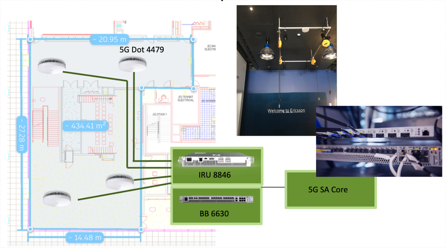
Figure 11: Our mid-band Stand-Alone 5G Network
RC control latency
For a fair comparison of the two technologies, we run end-to-end measurements. That is, for control latency we measured stick-to-output-signal latency (STOL) and for video streaming glass-to-glass latency (GTGL).
To measure STOL, we started a timer when a button was pressed on the radio controller until the corresponding PWM signal or SBUS channel changed on the output port of the receiver. We used a Raspberry Pi to send a trigger signal directly to the radio controller and then measure PWM signal and SBUS channel value changes on the receiver side and log the lag to a time-series database to calculate statistics and visualize the data. To avoid synchronization bias, we added a uniformly distributed random latency for every trigger picking a random delay between zero and the framerate (in our case 11ms for the car and 9ms for the drone).
For the RC car, we measured mean STOL latency of around 10ms.
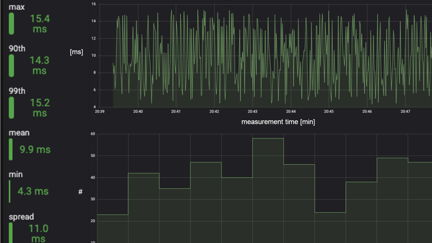
Figure 12: RC Car (PWM) Control Latency
For the RC drone, the average STOL latency was around 17ms. Since the typical frame rate of the SBUS protocol is 9ms, it is possible to reach latencies around that level. However, the popular radio system we tested only updates the channels every second frame, which was the reason for the longer delay.
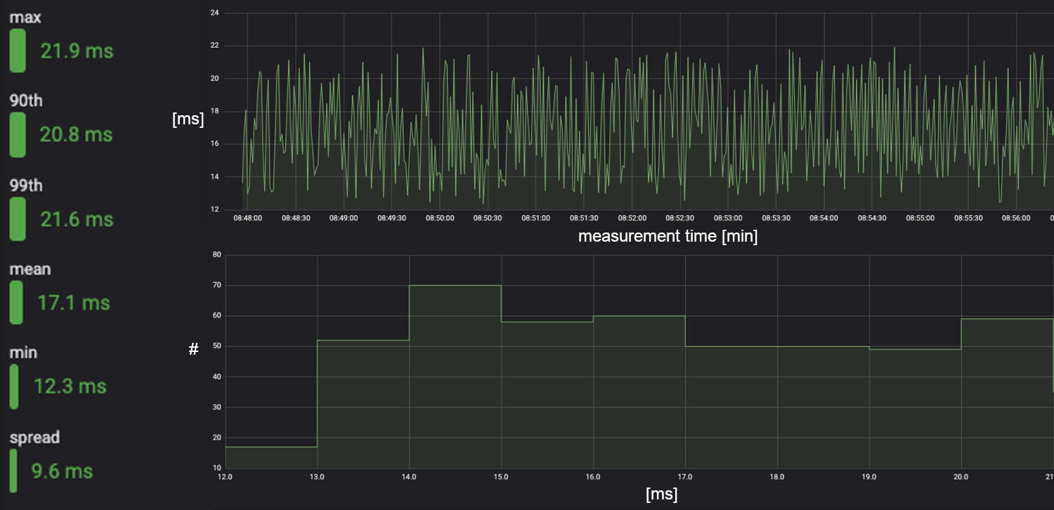
Figure 13: RC Drone (SBUS) Control Latency
5G control latency
We used the same setup to characterize 5G/IP STOL latency that we used for the RC measurements. In this case, the measurement system sent a trigger to the controller script which in turn picked up the signal at its next regular update and included the updated value in the control packet transmitted over the network. On the vehicle, our receiver script decoded the control packet and the new channel value was sent to the servo controller which in turn updated the PWM value on its output pins. In the case of the drone, the receiver script assembled the corresponding SBUS message and sent in over a UART connection to the FC of the drone.
In the case of the 5G car, the average STOL latency was around 16ms, which is very close to the RC performance. In fact, the reaction time difference is not noticeable.
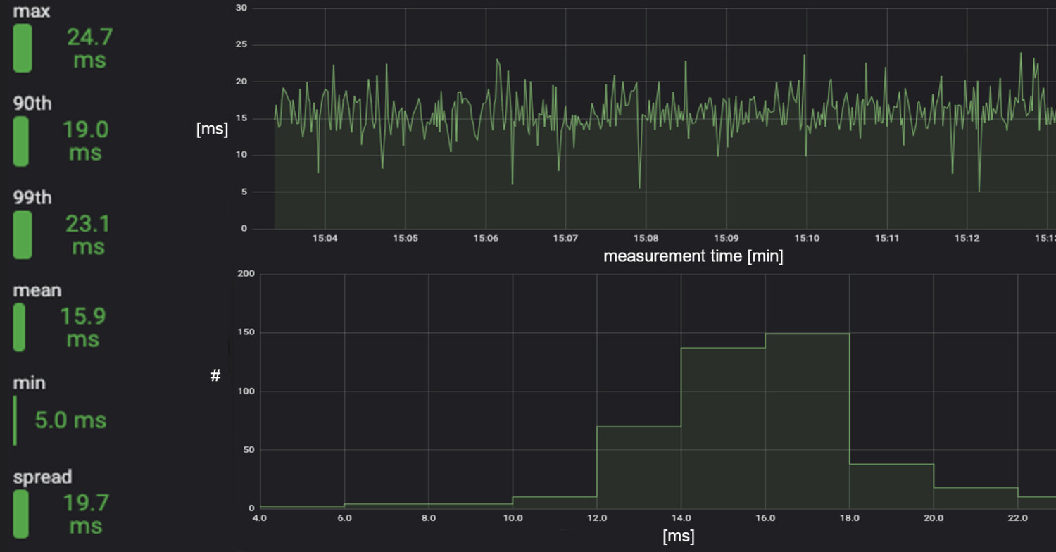
Figure 14: 5G Car (PWM) Control Latency
In the case of the 5G drone, our results show an average STOL latency around 16ms. The 5G based control latency is similar to the results of our RC measurements.
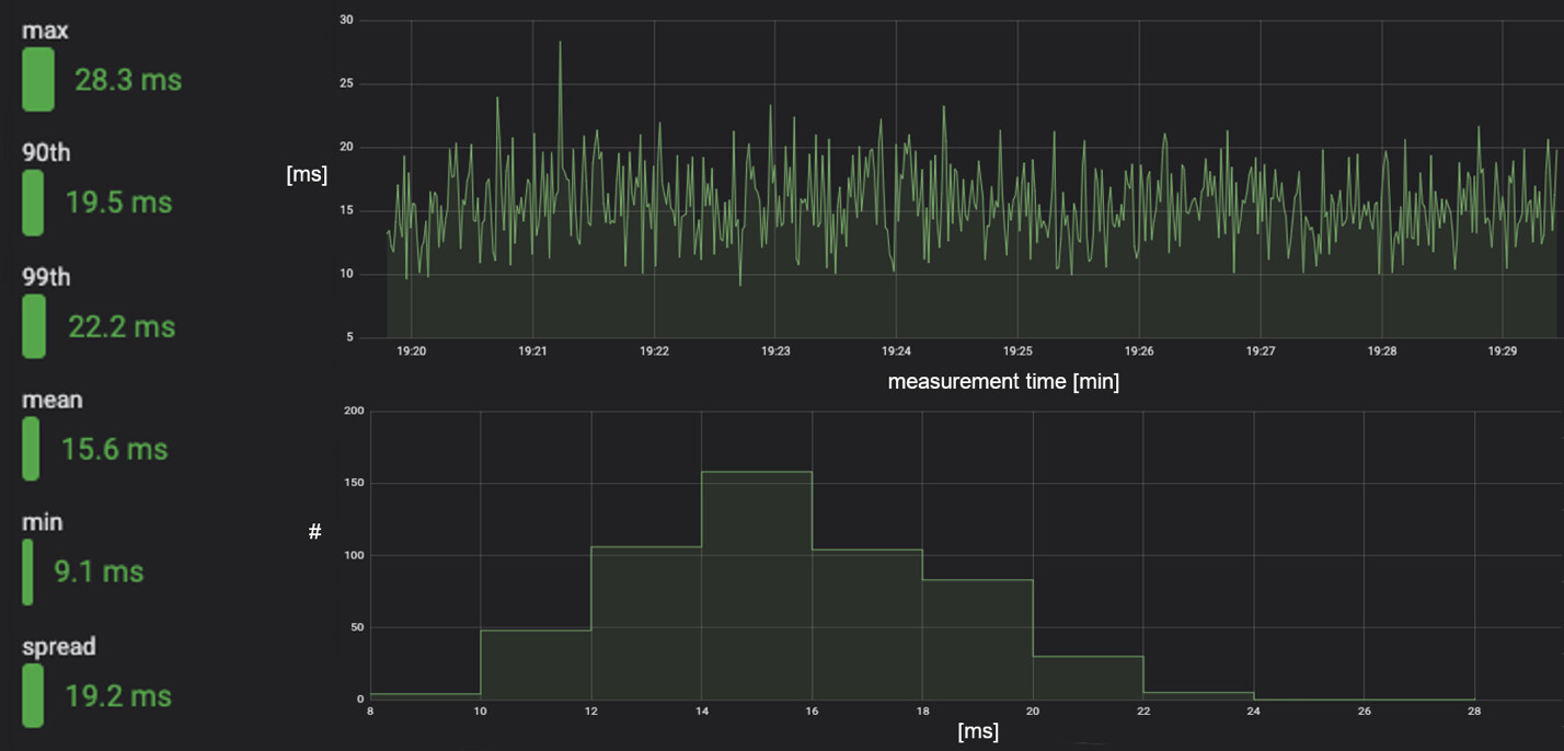
Figure 15: 5G Drone (SBUS) Control Latency
The 5G/IP controller performance can be improved by couple of milliseconds just by using C code instead of the Python scripts as part of the system. Using a real-time operating system instead of a basic Linux distribution on the Raspberry Pi would yield additional improvements in latency and jitter. Nevertheless, the measured performance is indicative of what can be achieved already by just using simple code and a basic developer-friendly Linux operating system.
RC/analog first-person-view video latency
A typical RC first-person-view (FPV) video system has three components. An analog camera connected to a radio transmitter that sends the native NTSC/PAL signal to a receiver that displays the video on a monitor or head-mounted-display/goggle. Video monitors are typically used by long-distance pilots while goggles are used in drone racing. Since the system is analog there is no delay added by compressing the image and packaging it for transmission. The image quality is according to NTSC/PAL specifications: PAL: 720 x 576 at 25fps and NTSC: 720 x 480 at 30fps. However, both standards use interlacing, meaning that first odd then even lines are read, transmitted, and displayed. This effectively doubles the perceived framerate to 50fps and 60fps respectively.
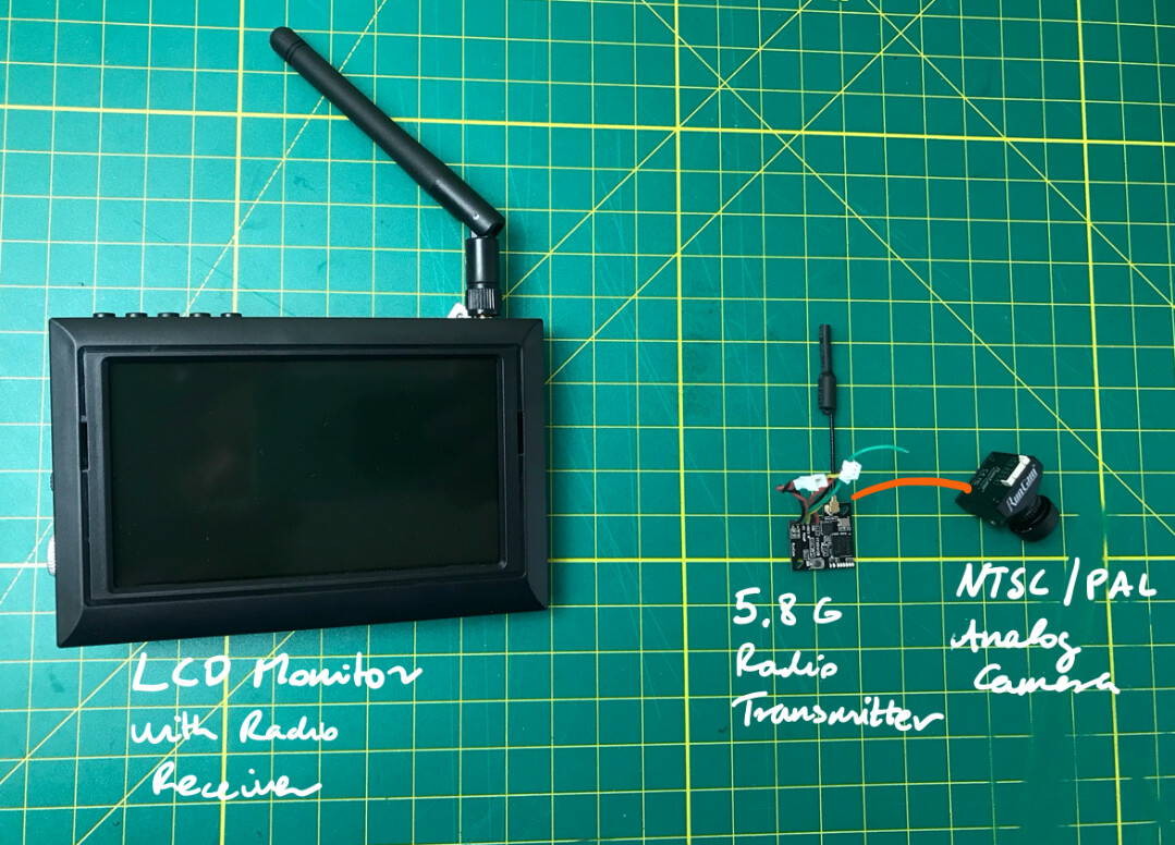
Figure 16: RC FPV Video System
To systematically measure end-to-end video latency and collect a large number of data points we run automated measurements. We used a Raspberry Pi to trigger a LED light source placed in front of the camera and subsequently capture the signal from photodiodes placed in the middle of the display on the receiving side.
The average glass-to-glass latency (GTGL) of the entire RC/analog FPV video system was about 10ms.
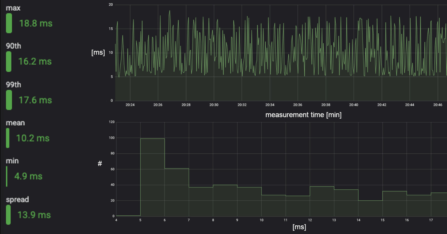
Figure 17: RC Video Latency
Digital first-person-view video latency
To add video streaming support to the 5G/IP system we attached a Raspberry Pi v2 camera. This configuration makes use of the hardware-accelerated H.264 video encoder of the board and also bypasses the CPU making the best use of the available hardware. The lowest latency capture is at the 640x480 camera mode. Since the 640x480 resolution is a good match of the analog video resolution, we used this mode in our tests. As a baseline we used 60fps video. For the receiver, we use another Raspberry Pi 4. We used GStreamer to test a set of video-pipelines and optimize the streaming configuration for low latency.
To set a baseline reference performance we first tested video streaming over a fixed 1Gbps Ethernet network. Both sender and receiver were Raspberry Pi 4 boards, streaming 640x480 H.264 encoded video at 60fps. The display used had 60Hz refresh rate. Our first results showed 67ms of average latency.
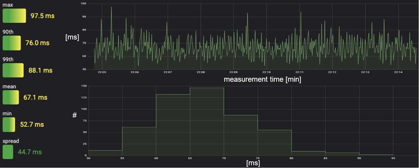
Figure 18: Digital Video Latency over Ethernet at 60fps
There are a few simple improvement possibilities. For example, increasing the framerate and using a higher refresh rate monitor. To test it out, we increased the framerate from 60 to 120 and tested the setup with a 240Hz refresh rate gaming monitor instead of the 60Hz office display used in the previous measurement. To be able to decode the H.264 stream at 120fps in hardware and to support the display with 240Hz we had to replace the Raspberry Pi 4 on the receiver side with a Jetson Nano. However, the onboard Raspberry Pi 4 remained the same as it does support 120fps video capture and H.264 encode. With these simple changes we reduced the average latency to around 56ms over wired 1Gbps Ethernet. This simple change resulted in a performance improvement in the order of 10ms.
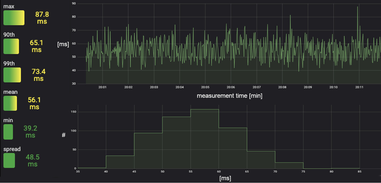
Figure 19: Digital Video Latency over Ethernet at 120fps
Since the one-way network latency over our 5G network is around 3-4ms, we can note that the bottleneck is not the 5G network rather the other components of the digital video streaming pipeline. As the above example indicates there are likely more improvement possibilities of the end-to-end pipeline to chip away additional milliseconds.
Over the 5G network we tested the video streaming configuration with 60fps and 60Hz monitor using two bookended Raspberry Pi 4s. The average GTGL latency was 70ms (cf. 67ms in the case of Ethernet). Practically, the difference between the Ethernet and 5G results was the 3-4ms one-way latency introduced by the network. This is negligible compared to the delay added by the other components of the video streaming pipeline.
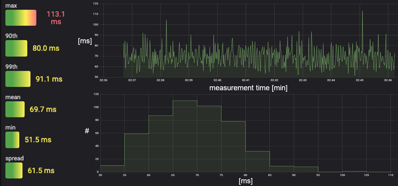
Figure 20: Digital Video Latency over 5G at 60fps
We did test both the car and drone platforms using the FPV video driving/flying around our 5G racetrack and compared our perceived performance between the RC and 5G video streams. While there is a lag with digital video, the 70ms latency is still practical for remote control and the vehicles can be well maneuvered at speed around the racetrack.
Post-race review
When we control the car and drone with direct visual view the total loop latency is the STOL latency plus the speed of light, which practically gives us the STOL latency. In this case, total RC control loop has a lag of around 10-15ms while the 5G control latency is around 15ms. The 5G control matches the RC performance. Furthermore, this is a latency level that is perceived as instantaneous.
When we use the FPV video, the end-to-end loop lag consists of the sum of STOL and GTGL. For the RC, we are in the ballpark of 20-25ms, which is very fast. When using digital video streaming with low-cost components, we can achieve around 85ms average loop latency. While this is inferior to the analog video of RC systems, it is already below the 100ms real-time “usability” limit. Considering that we could reach this latency level with a low-cost $50 single-board computer and basic Python scripting, the DIY racing community can surely improve upon this performance going forward.
When it comes to 5G, we are developing new features to provide stringent latency and jitter boundaries for time critical applications. If we combine those features with improved digital video codecs tailored for low latency streaming, we know that we can further close the gap to analog FPV systems.

Together with Qualcomm and Verizon, we recently pushed latency to its limits in high-band millimeter wave on another 5G Hobby racetrack. Watch the video to see what happened.
Learn more
Find out what happened when we tested 5G latency in elite sports and music.
Learn more about Ericsson D-15.
Explore 5G