Joint communication and sensing in 6G networks
Researcher, Systems and standardization
Researcher, Systems and standardization
Researcher, Systems and standardization
The inclusion of sensing capabilities in a communication network is a very promising area that presents many opportunities and challenges. There are use cases applicable to improving the performance of the network itself, but also exciting use cases where the spatial sensing can be offered as a service to users or applications that are external to the network.
The main advantage of the communication network in terms of future sensing is that most of the infrastructure is already in place with transmit/receive (Tx/Rx) nodes, providing full area coverage as well as a good interconnection between nodes, which facilitates a multi-static sensory mesh. Hence, the sensing can be provided almost ‘for free’.
Ericsson has teamed up with NXP Semiconductors to look into potential new use cases for a network where communication and sensing functionalities are fully integrated into the same transmission/reception nodes. Together we will also investigate implementation aspects of such future systems and evaluate the technical challenges and opportunities for JCAS use cases. Click here to read about NXP’s view on this topic.

6G technology and its evolution
Read about Hexa-X, the European 6G research project driven by Ericsson and Nokia
Click hereSensing in a network setting
With the evolution of 4G to 5G, the spectrum allocations have expanded towards higher frequencies. This trend will continue and communication spectra in the sub-Terahertz region will likely be available as some of the frequency bands for 6G deployments. With the introduction of these new frequencies, the potential for very accurate sensing based on radar-like technology arises. That is, reflections of transmitted signals are received in the network and processed to yield spatial knowledge of the physical surroundings.
Sensing as an integrated capability is of interest throughout the frequency range used by mobile communication networks, starting as low as 700 MHz, where the lowest time-division duplex (TDD) bands are located. Having said that, this blog post will mainly focus on the higher, sub-Terahertz bands.
At these frequencies, the communication network must employ beamforming of the transmitted signals to concentrate and direct the signal energy to a specific geographical area where the intended receiver is located. The inter-site distance (ISD) necessary to create full geographical coverage without beamforming would be prohibitively short. To create full coverage, beamforming combined with beam sweeping over time can be employed. Hence, the mechanisms for beamforming are already present in the network and can then also be utilized for sensing.
The benefits of integrated sensing
What can be achieved from a technical standpoint and what are the use cases for sensing?
These future sensing capabilities could be used to enhance the performance of the network itself by providing optimization input for network steering. For example, the sensing would be able to detect objects that (temporarily) obstruct the direct propagation path between a transmission node and a device. This input would be very useful for rapid beam steering, such that the network could instead utilize another, reflected beam or switch to a different transmission point for communication with this device.
Broadening the scope to sensing as a feature offered by the network, all kinds of spatial monitoring is of interest. Let’s first look at the basic sensing capabilities. Depending on the frequency, the resolution of the sensing image that can be obtained varies. For frequencies around 100 GHz and their typical bandwidths it is possible to reach below 1 cm. However, the resolution also depends on the reflective properties of an object as well as the proximity to other nearby objects and their reflective properties. In comparison to a visual image from a camera, a sensing image based on the reflections from the transmitted signals is quite crude. However, this sensing method offers other attractive properties that a camera cannot provide.
By measuring the delay of the return echo in the line-of-sight path between the transmitter and the object, the distance to the object can be calculated, and therefore, its position. Similarly, by measuring the Doppler shift in the received echo, compared to the transmitted signal, the velocity of the measured object can be calculated.
Another useful feature of sensing based on radio signals is the fact that it also works in complete darkness. It can also ‘see’ in rain or fog, but with somewhat degraded performance, since the water particles in the air will attenuate the signals, especially at higher frequencies.
Interesting future sensing use cases
A traffic monitoring scenario is a concrete use case for future sensing, where not only the positioning capabilities would be valuable, but also the ability to measure the speed of objects. For example, we could have two or three Tx/Rx nodes overlooking an urban street intersection. Such a concrete scenario would provide a useful set-up for analysis of the interplay between communication and sensing parameter choices.
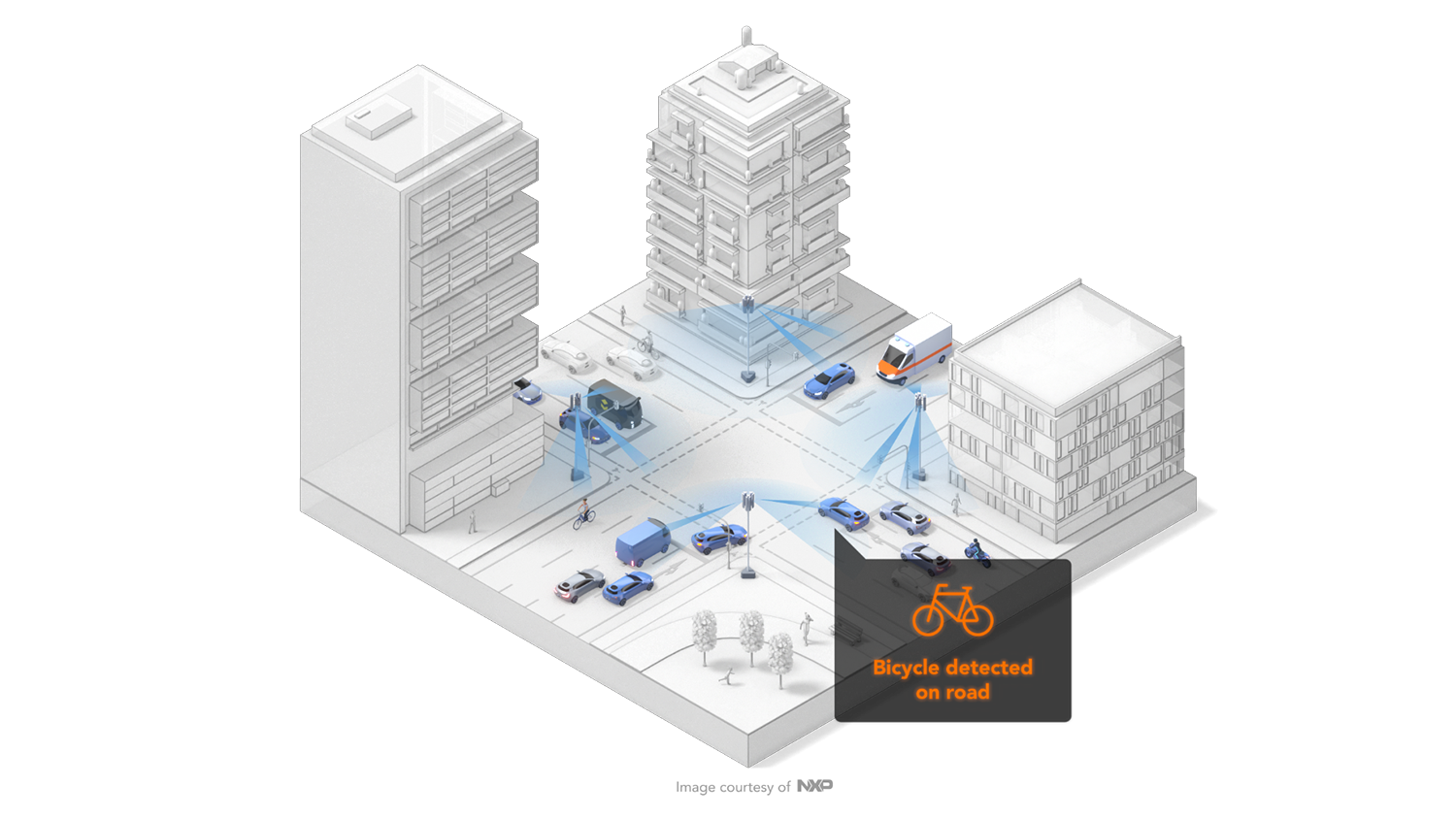
Figure 1: Traffic monitoring use case.
Aspects of sensing signal design, necessary modifications to the radio receiver, and how the integration of sensing and communication can be carried out, as discussed below, could be investigated. This use case also exemplifies sensing in a network setting where the fact that we have several Tx and Rx nodes overlooking the intersection can be explored. The sensing processing chain can also be evaluated – for example, evaluating which sensing functionality is suitable for edge processing in each radio receiver and which is a better fit for joint processing in a common node.
Another example of positioning on a smaller scale would be estimation in a manufacturing scenario. Precise position estimation around a factory robot would help determine where a robot arm is located and if there are any interfering objects, such as a human, inside its intended space of motion. The position estimation of objects that a robot should grip, or of objects that the robot has released, would also be a useful feature.
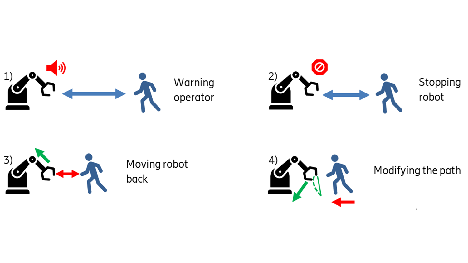
Figure 2: Sensing use case to monitor the immediate vicinity of a manufacturing robot.
Fully immersive sensing
Taking spatial sensing to its full extent, there are several use cases where the entire surroundings of the transmitter would be mapped out. When creating a so-called ‘digital twin’ of the radio network environment, the sensing information would provide a lot of valuable data. The digital twin is a virtual representation, or model, of the physical world that can be used to simulate and predict network performance. It can be used to evaluate novel network algorithms or plan the deployment of new nodes.
Obviously, a digital twin can be used to model and evaluate other aspects of the real world not at all connected to the network operation. In this case, the sensing data provided by the network is only used to build and refine the digital twin but without feedback to the network. The digital twin is subsequently used for simulating other aspects of the surroundings. One such example would be extended reality (XR) scenarios. You can play a game that appears to take place in your real-life environment. As you move in the physical world, the projected environment seen in the game, provided by the virtual twin, changes accordingly.
Joint communication and sensing in the network
When utilizing a communication network for sensing there are a number of implementation aspects to consider. The frequency range described in this blog post falls into the region of traditional radar. Regardless of network frequency, the principles of spatial sensing rely on detecting the reflected signal and analyzing it. Hence, it is convenient to borrow some of the already established terminology from radar technology.
There are different ways one can view adding sensing as a capability to the communication network. On the one hand, it can be seen as utilizing the existing network with very few tweaks. The sensing is then introduced by adding dedicated sensing processing of received signals already present for the communication. This means no changes are needed to the communication functionality, only additions in terms of sensing processing at the receiver side.
On the other hand, adding sensing can also be seen as integrating an existing radar-based system into the network. Then it becomes more of a question of how to share the available resources in time, frequency, available antennas, transmission power, processing capabilities, and so on. This results in a performance trade-off between the communication capacity and the sensing capabilities. Most likely, the preferred approach is somewhere in between. As much of the communication network as possible is used but with some modifications and additions to accommodate the sensing aspects.
Networks are well suited to provide sensing capabilities
In radar terminology, the terms ‘monostatic’ and ‘bi/multi-static’ are used. Monostatic means that the transmission and reception points are the same. That is, the transmit antenna(s) is first used to transmit a sensing signal (a ‘radar pulse’), the return echo of which is then received by the same antenna(s), or alternatively, the transmission/reception antennas are separate but co-located. Bi/multi-static means that the receiving antenna(s) is not the same as the transmitting antenna and that they are in different locations.
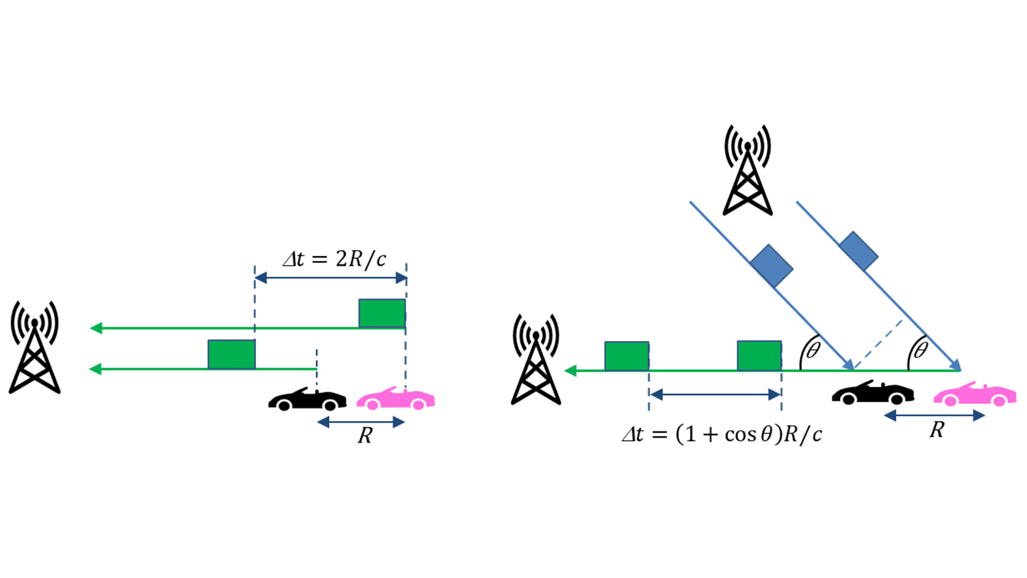
Figure 3: Monostatic (left) and bi-static (right) operation. The time Δt between received pulse echoes gives the distance R between the target positions. Here, ‘c’ is the speed of light.
A communication network consists of many nodes that together provide area coverage. Hence, the infrastructure for a multi-static sensing network is basically already in place. Several receiving locations can be used to receive the transmission echo from a single, or several, nodes. There are multiple sensors out there with the possibility to sense the reflections in different directions from one or more transmission nodes. The network nodes are already connected via the backhaul and core network, so the interconnect necessary for sharing radar pulse configurations and sensor echoes, possibly locally (pre-)processed, with other nodes or a centralized sensing node is available.
In the multi-static scenario, a framework for synchronization between nodes is needed, both to keep track of when to listen for the transmitted signals and to coordinate the transmissions to keep inter-node interference under control. Node-unique reference signals that identify the transmitting node are also needed. This is, however, already present in the context of the communication network. An analysis of the requirements to handle the increased data traffic between nodes and the additional processing power in the nodes must be carried out.
Radio implications in a monostatic scenario
In the context of traditional radar applications, the monostatic set-up is very common. This is the classic situation with a moving radar platform (airplane, ship, car, etc.) that employs radar for target location, collision avoidance, and other types of mappings of the surroundings. The monostatic set-up can be used in a communication network as well, but it adds some requirements on the radio.
A radio in a monostatic set-up needs to have some transmit-to-receive (Tx-to-Rx) cancellation mechanisms. This is needed because the transmitted signal (the ‘pulse’) must have a certain duration in time, otherwise it will have infinite bandwidth; pulse duration is inversely proportional to its bandwidth. What happens is that when the echo of the first part of the pulse returns from (relatively) nearby objects and arrives at the receiver, the transmitter is still transmitting the pulse. The Tx-to-Rx cancellation blocks the transmitted pulse (as much as possible) from entering straight into the receiver circuit, which would result in over-steering and drowning of the echo that we are interested in. The Tx-to-Rx cancellation can consist of analog filters, digital signal processing, and spatial solutions such as using different antenna panels.
If the pulse duration is short enough and/or the nearest reflective objects are at a sufficiently large distance from the transmitting antenna, Tx-to-Rx cancellation may not be needed. However, in a radio where the same antenna elements are used for transmission and reception, the switching time from Tx to Rx must still be fast enough to capture the first returning echoes. Communication radios are typically not constructed with extremely fast switching times since it is not needed.
Sensing capabilities at different frequencies
There are pros and cons of employing sensing at different frequencies. The attenuation of the radio propagation increases with higher frequencies, therefore requiring shorter distances between transmission sites to achieve area coverage. Nationwide rollouts will be done using low/mid-frequencies while the higher frequencies will be used for hotspots where (extremely) high communication capacity is needed. Hence, the opportunity for sensing with coverage ‘almost everywhere’ which comes ‘for free’ as part of the network will be available at low/mid-frequencies only.
On the other hand, the sensing capabilities in terms of achievable spatial resolution increases with increased frequency. The amount of detail that can be captured depends on the wavelength, as described by the equation λ=c/𝑓, where c is the speed of light and 𝑓 the frequency. This means that the best spatial sensing would be available in high-frequency hotspots.
The distance resolution is inversely proportional to the bandwidth. Hence, better distance resolution can be more easily achieved at higher frequencies where much wider bandwidth allocations are available.
The higher the frequency, the larger the number of antenna elements that can fit in a given area, since the inter-antenna-element distance is proportional to λ. With more antenna elements the angular resolution also increases since the beams can be made narrower. It is not unreasonable to think that it is in the high-frequency hotspots that the demand for high-quality sensing is the highest, which makes for an attractive fit.
As mentioned earlier, this type of sensing also provides location estimation of objects. There are positioning mechanisms already present in 4G/5G networks, but they require ‘active’ targets. A device must communicate with the network to enable the determination of its location. By relying on measurements of the return echo of the transmitted signal, the network can localize passive objects.
Transmit signal design
A common design goal of radar signals is that they are suitable for distance and velocity estimation and that they provide good spatial resolution of the objects being sensed. For digitally modulated radar (DMR), the possibility to use code-division multiplexing (CDM) is also important.
The reference signals that are used in communication systems are designed based on somewhat different requirements. Primarily, they are pilot signals present for channel estimation at the receiver. This includes time- and frequency-error estimation, as well as the ability to use CDM between different users. Certain other properties, such as low peak-to-average power ratio of the reference signals, are also taken into consideration.
Consequently, an important aspect of JCAS is the reference/sensing signal design. How well-suited are the traditional reference signals in communication networks for radar-like sensing? Can their return echoes be used to estimate velocity? What type of spatial resolution can they offer? And so on.
Vice versa, how useful are traditional radar pulses when it comes to channel estimation? It is not unlikely that new transmit signals will be designed that take both sensing and channel estimation properties into consideration. If these new signals can be multi-purpose, more bandwidth would be available for data transfer. Since the modulation in 6G is expected to be based on orthogonal frequency-division multiplexing (OFDM) – rather likely a DFT-spread variant of OFDM – it is also of interest to understand the sensing properties of such a signal. In other words, how suitable is it to use an OFDM-based pulse for radar-like sensing?
Now let’s get into some mathematics by looking at the shape of the transmitted sensing signal, which is interesting to explore. If you are not interested in the details, feel free to skip to the next section. In traditional radar of the continuous-wave frequency modulated (CWFM) type, the signal is typically a so-called ‘chirp’, which is a signal that sweeps in frequency over the allocated bandwidth. The transmitted signal:
ST(𝑡) = A*cos(2𝜋 (𝑓C + 𝑓M(𝑡))𝑡),
Where 𝑓C is the carrier frequency and 𝑓M(𝑡) is the function that sweeps the frequency over the transmission duration T.
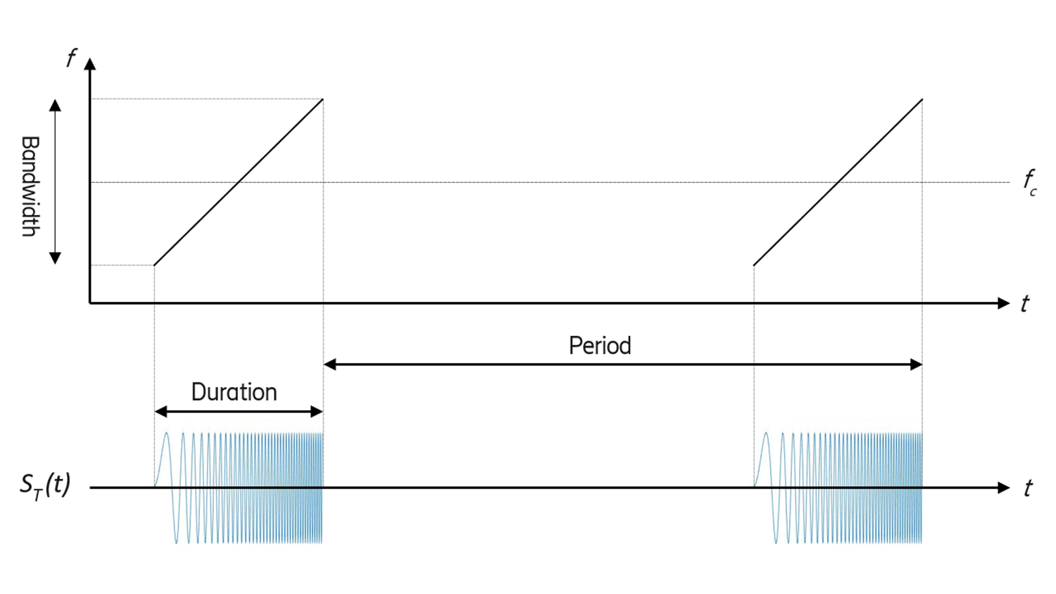
Figure 4: Radar chirp that sweeps the allocated bandwidth.
A more modern type of radar utilizes CDM. Here, the basic signal is sinusoidal, but its phase angle is altered by a sequence of discrete phase values, given by 𝜙(𝑡), during the transmission period T.
𝑠T(𝑡) = A*cos(2𝜋𝑓c𝑡 + 𝜙(𝑡))
The so-called spreading code 𝜙(𝑡) is constructed using a periodic or pseudo-random sequence of chips, (e.g., 1, 1, -1, 1, -1, -1, 1, -1,...) that is mapped to phase values, (e.g., 1→0, -1→𝜋) which stay constant during the chip duration Tc . 𝜙(𝑡) is then formally defined as:
𝜙(𝑡) = 𝜙k for k*Tc < t ≤ (k +1)×Tc , for k = 0, 1, ...
where 𝜙k is the k:th value in the sequence of phase values. The resulting signal has a bandwidth that is proportional to the inverse of the chip duration.
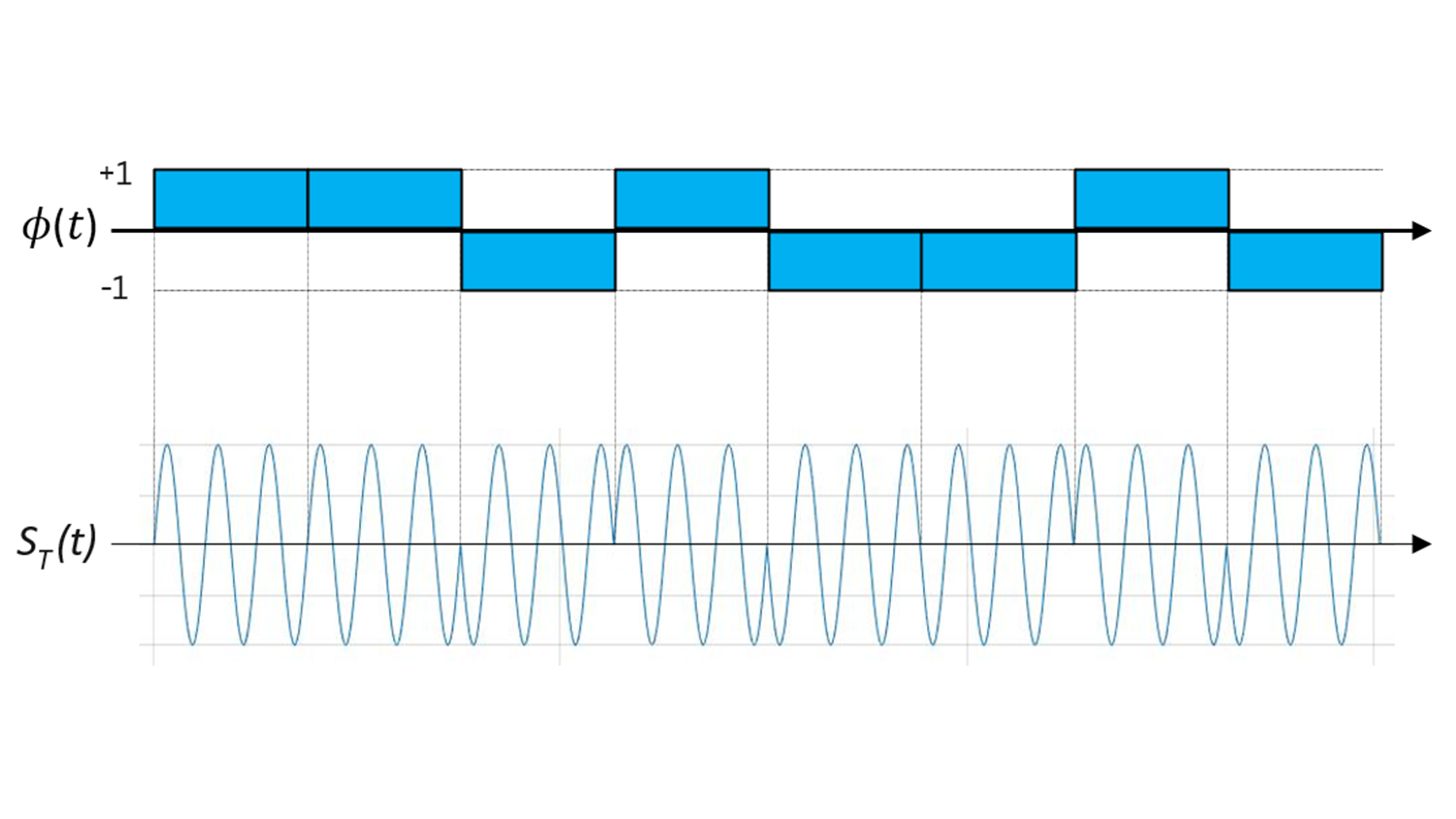
Figure 5: Illustration of how the spreading code affects the phase of the transmitted signal.
By choosing spreading sequences that are orthogonal over T, CDM of multiple radar pulses can be achieved. This enables a receiver to separate different pulses that are transmitted simultaneously over the same bandwidth.
Smooth integration of communication and sensing
Another hybrid approach would be to use the reference signals dedicated for communication only when transmitting data and transmit dedicated sensing signals in all other directions where no communication is currently ongoing. (Suboptimal) sensing could still be performed in the direction of the communication, but reliable data transfer is prioritized. It requires digital beamforming or multiple analog beams on the transmit side to implement this approach to spatial-division multiplexing (SDM). One can also think of making compromises in the actual beam design such that it is good enough for communicating with a given device and at the same time provides the best possible sensing coverage.
Communication and sensing can also be integrated into the same system in a manner whereby the different functionalities are more clearly separated, which is more of a co-existence strategy to the resource sharing. Time-division multiplexing (TDM) or frequency-division multiplexing (FDM) can easily be implemented by dedicating separate time slots or separate frequency allocations to communication and sensing, respectively. The division of resources then becomes a compromise between desired sensing and communication performance. This trade-off could be adaptively controlled such that more resources are spent on sensing if the communication load is low.
Finally, there are some low-level architectural aspects of bringing sensing capabilities into a communication network. The need for faster Tx-to-Rx switching as well as Tx-to-Rx cancellation in the radio have already been mentioned above.
The signal-processing chain inside the radio needs to be carefully considered since the type of processing is different for communication and radar/sensing. In both 4G and 5G, the communication is based on OFDM, which means that most of the processing is done in the frequency domain. Hence, the received signal is transformed to the frequency domain (using a Fast Fourier Transform; FFT) early on in the processing. A similar situation is likely for 6G as well. However, in the sensing case, some of the early processing involves time-domain correlation with the transmitted signal. The uncertainty in the timing of the received signal also makes the transformation to the frequency domain challenging. Hence, adding efficient processing for sensing will require some ‘under-the-hood’ changes or additions in the radio receiver.
Conclusion
The future sensing capabilities perceived in 6G networks present many opportunities. There are multiple use cases where spatial sensing can be used to improve the performance of the network itself, as well as provide new, exciting sensing services to external users and applications. There are, of course, also technical challenges to handle.
The infrastructure of Tx/Rx-nodes in an area-covering network, in combination with good interconnection between the nodes, provides an excellent setting for a multi-static sensory network. Since this infrastructure is already in place in a communication network, the addition of sensing capabilities can be provided in a cost-efficient manner.
We, Ericsson together with NXP, are excited to explore the potential of JCAS and expect it to become an important part of future 6G systems. It will be very interesting indeed to evaluate different solutions with new use cases and provide the best possible sensing capabilities from the network.
Learn more
Read our blog post Hexa-X: 6G technology and its evolution so far.
Read our whitepaper on ever-present intelligent communication.
Explore 5G