









The evolution of MINI-LINK: setting the stage for Radio Link Bonding
- Radio Link Bonding (RLB) is the next deep dive in the 50-year MINI-LINK history of innovations.
- A simple, elegant and incredibly effective solution to a problem that Link Aggregation Groups (LAG) could never solve in a microwave environment. It enabled operators to fully benefit from the extra spectrum they were paying for and is still relevant in modern networks.

Senior Specialist Wireless Transport
Senior Specialist Wireless Transport
Senior Specialist Wireless Transport
The point‑to‑point microwave market, and MINI‑LINK in particular, really took off in the early 1990s. At that time, mobile networks were expanding at an unprecedented pace following the introduction of second‑generation digital systems. Thousands of new base stations were rolled out across the world, each one needing reliable backhaul to connect to the core network. Microwave quickly proved to be the most practical and scalable way to make that happen. A MINI‑LINK hop could be deployed in a fraction of the time required for fiber or copper, especially at sites with no existing infrastructure, delivering high‑quality connectivity over tens of kilometers almost instantly.
Back then, mobile traffic was almost entirely voice. Today, of course, it’s a very different landscape. Modern networks are driven by data; high‑speed, always‑on, bandwidth‑hungry data. Each new generation of mobile technology has brought new capabilities, new expectations and new demands on the transport layer. This evolution has transformed backhaul from simple circuit‑based connections into sophisticated packet networks, and MINI‑LINK has grown alongside it: first, through hybrid solutions blending circuit and packet, and, today through fully packet‑based microwave systems.
Over the years, MINI‑LINK has continued to introduce features that make better use of spectrum, increase capacity and extend packet‑network capabilities into the radio domain. Each of these innovations has helped Communication Service Providers (CSPs) meet the demands of ever‑increasing traffic volumes and higher service expectations.
One of the most important of these innovations, especially in today’s high‑capacity microwave networks, is RLB. In this blog, I’ll share my perspective on how we got here, why it matters, and what I’ve learned over more than three decades of working with MINI‑LINK.
“Why on earth are we doing this?”
When I first joined the MINI-LINK team in the early 1990s, one of my initial assignments was to help adapt an existing product for a new market. At first glance, the task felt… puzzling. The customer interface delivered about 6 Mbps, yet we were supposed to pad it with meaningless data to reach 8 Mbps before sending it over the air.
It was one of those moments when you look around the room and think, “Why on earth are we doing this?”
The answer, as it turned out, was simple: regulations.
Radio waves don’t stop politely at national borders, so every country must follow international agreements to avoid interference and chaos in the spectrum. The most important of these is the ITU Radio Regulations (RR), which form the foundation for national rules around the world. In this particular case, the channel plan allowed only 4 Mbps and 8 Mbps wireless connections. Some national regulators interpreted that to mean communication service providers (CSPs) must always use the maximum channel capacity—even if the actual traffic was lower. So, there we were, padding perfectly good data streams with “nonsense” bits just to satisfy a regulatory interpretation.
Faced with the choice of either modifying the product or trying to convince regulators to update their national rules, the decision was obvious. Updating legislation can take years, sometimes decades. Making the product adaptation was, in comparison, the easy part.
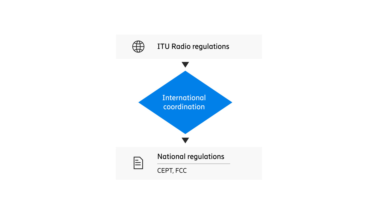
Figure 1: Radio regulations are agreed upon through international collaboration and implemented nationally
When point-to-point microwave started to roll out at scale for digital mobile backhaul in the early 1990s, the new systems didn’t start with a blank sheet of paper. Far from it. They had to fit into channel plans originally created for analog services, plans that were already deeply embedded in national regulations and spectrum planning. And with the rules established, CSPs could finally start deploying digital mobile networks at speed powered by the rapid rollout capabilities of microwave backhaul.
And, just like that, people everywhere could start making wireless phone calls from practically anywhere to pretty much anywhere. So, brave new world. End of story?
(As we soon discovered … not quite!)
New barriers
As mobile voice was becoming part of everyday life in the 1990s, the internet was rapidly reshaping the world around us. It was only a matter of time before people wanted that same data experience to follow them when they left their desks.
Data first appeared in mobile networks through simple text messaging in 2G. Then came GPRS, the first dedicated packet data service for GSM. But the real acceleration arrived with 3G, and especially with High-speed Packet Access (HSPA). That’s when the shift from voice centric to datacentric mobile networks truly took off.
This surge in packet traffic pushed microwave backhaul to evolve quickly. Hybrid links and adaptive modulation offered new ways to increase throughput for data services while still maintaining the high availability required for voice. These were important milestones.
But one significant limitation remained:
Spectrum availability and fixed channel allocations still capped how much backhaul capacity we could deliver.
To overcome that barrier, the industry turned to a clever solution: dual polarization. By transmitting one signal on horizontal polarization and another on vertical polarization, operators could effectively double their spectral efficiency. Polarized antennas provide good discrimination between the two signals, and any residual interference can be mitigated using Cross Polar Interference Cancellation (XPIC).
A major gain — but it came with a new challenge. Suddenly, we had two physical radio paths carrying data, but still only one logical point-to-point backhaul connection that the transport network expected. So, the question became:
How do we combine two physical microwave links into a single backhaul interface?
One possibility is to use LAG as defined by IEEE 802.3ad. In a LAG, packet flows are distributed across physical links based on their source and destination addresses. Once a flow is assigned to one link, it stays there. LAG works well in many parts of an IP network. But in mobile backhaul, it runs into a practical problem.
Most traffic is encrypted, meaning very few flows are visible to the microwave layer. If you can’t see the flows, you can’t balance them efficiently. In real microwave deployments with two equal links, LAG typically provides only about a 50% capacity gain, despite consuming 100% more spectrum.
Not exactly the efficiency CSPs hoped for. There had to be a better way. But what would that look like?
Breaking the barriers
RLB is, at its core, about changing perspective.
Where traditional LAGs make decisions based on traffic classification, RLB flips the model. LAG tries to balance packet flows without knowing anything about the radio conditions underneath. In microwave backhaul; where link capacity can vary with modulation, weather, or interference, that approach quickly reaches its limits.
RLB, on the other hand, makes its decisions based on available physical layer capacity. Instead of classifying flows, it focuses on using every bit of radio spectrum as efficiently as possible. It doesn’t need to know what the data means; only how to slice it, distribute it, and reassemble it intelligently.
The first implementation of RLB in MINI-LINK TN was surprisingly elegant. It consisted of four simple steps:
- Segmentation in the transmitter
Packets are broken into smaller segments and each segment is tagged with a sequence number.
- Distribution in the transmitter
Segments are sent across whichever link has free capacity at that moment. No flow awareness needed — just efficient use of the radio.
- Buffering in the receiver
Incoming segments are temporarily stored to allow for differences in arrival time between the links.
- Reassembly in the receiver
Segments are sorted by their sequence numbers and stitched back together into the original packets.
And that’s really all it took.
With this straightforward approach, MINI-LINK could use almost 100% of the added spectrum capacity created by dual polarization. The overhead from segmentation and sequencing was tiny, only 1–2% of total aggregated capacity.
The result?
A simple, elegant, and incredibly effective solution to a problem that LAG could never solve in a microwave environment. Suddenly, CSPs could fully benefit from the extra spectrum they were paying for.
Problem solved — and in hindsight, such a beautifully practical idea.
RLB — a good thing, and a very useful one
Once RLB was in place, the XPIC challenge was essentially solved. Suddenly, we could make full use of both polarizations — efficiently, predictably and without the limitations of LAG. At the same time, standardization was slowly evolving, opening for wider channels and new frequency bands.
But as often happens in our industry, traffic demands grew faster than standards and regulations could keep pace. And much of that regulatory framework was still rooted in a 2G circuit switching mindset. While the world was moving into high capacity packet transport, the rules hadn’t quite followed along.
Here, again, RLB proved to be incredibly useful.
Traditionally, two polarizations bonded together form what we call a 2+0 configuration; two active links, no dedicated protection link, combined to act as a single higher capacity connection. But RLB is not limited to dual polarization, and it certainly isn’t restricted to two identical links. The beauty of RLB is its flexibility:
- You can aggregate links of different capacities
- You can aggregate links on different polarizations or channels
- You can aggregate more than two links. In practice, almost any number that your hardware supports
That meant CSPs could reclaim and recombine whatever spectrum resources they had available; building backhaul capacity that matched real demand instead of regulatory legacy. It opened an entirely new level of freedom.
RLB was first introduced in the modular, node based MINI-LINK TN. With Ethernet switching, and the bonding engine running on the Node Processor Unit, it quickly became a commercial success. It offered precisely what CSPs needed at the time: a flexible, scalable, packet ready platform for building the next generation of mobile backhaul networks.
Later, with the arrival of MINI-LINK 6600, we introduced a significant architectural shift. The RLB function moved from the node processor down to the modem itself. Each dual carrier modem could now independently support 2+0 RLB, and two companion modems could be paired for 4+0 RLB.
This created a true pay as you grow model, capacity and bonding capabilities increased simply by adding more modems. For most deployments, 4+0 is more than enough. But for CSPs needing even more aggregated bandwidth, MINI-LINK 6600 introduced hierarchical Radio Link Bonding (hRLB).
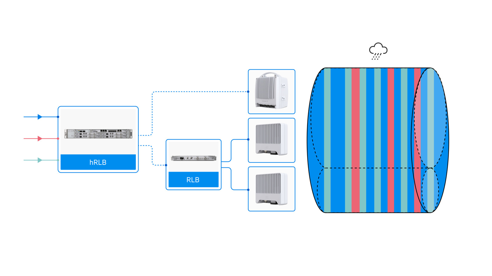
Figure 2: MINI-LINK system with hRLB and RLB
And hRLB doesn’t just let you combine RLB groups. It unlocks much more.
Taking it to the next level
Around 2010, a new wave of backhaul innovation arrived with the introduction of millimeter wave (mmW) equipment in the 70/80 GHz E-band. Ericsson launched the MINI-LINK PT 6010, followed later by the MINI-LINK 6352, and operators welcomed them with open arms. After all, who wouldn’t be excited about 2000 MHz channels and 10 Gbps peak rates? For network planners, it felt like the future had suddenly arrived.
But as always with radio - there is a flip side.
At these high frequencies, propagation behaves very differently. Rain attenuation becomes a dominant factor; heavy rain can act almost like a solid wall to an E-band signal. Under identical conditions, you simply cannot achieve the same availability in the E-band as you can in traditional microwave bands such as 18 GHz. But here is a trick; if RLB is used to combine a high capacity E-band link with a high availability standard-band link, you will get the upside from both.
On their own, each link has strengths and weaknesses. But bonded together using RLB, they complement each other perfectly.
This is what we call Multi-band Booster: combining one band with superior propagation and another with superior capacity to achieve the best of both worlds.
You can read more about the details of Multi-band, and the story behind it, in next MINI-LINK blog.
Why hRLB is a perfect fit for Multi-band Booster
At this point, it’s worth revisiting something I mentioned earlier: the limitations of using LAGs for microwave bonding. LAG is blind to radio conditions and blind to available capacity. It just hashes flows. hRLB is different.
hRLB implements both flow awareness and resource awareness:
- Flow awareness ensures that packets belonging to the same flow as far as possible stay in order on the same link. Thus, minimizing the risk of reordering within flows.
- Resource awareness ensures that packets are steered towards the link that currently has capacity, ensuring optimal utilization of spectrum resources.
Combined, these capabilities make hRLB particularly powerful for multi-band boosting, where one link might be pushing 10 Gbps while the other offers a stable few hundred Mbps but with extremely high availability. hRLB ensures that:
- high capacity flows aren’t held back by the slower link, and
- the overall connection gets the best combined latency, throughput and resilience.
In other words:
High-capacity traffic rides the fast horse, and there is always a reliable one available for control, and other high priority, traffic.
Another elegant feature of hRLB is that it uses standard Ethernet frames. That means the hRLB packets can be carried across equipment that isn’t even aware of the protocol.
For CSPs, this opens up a huge practical advantage: They can upgrade an existing third party site to a Multi-band Bonding configuration simply by adding a MINI-LINK with hRLB enabled. No forklift replacements, no vendor lock in, no topology redesign.
It’s one of those small design choices that, in practice, makes the entire solution more flexible.
What will happen next then?
In this blog post you have learned that
- RLB unlocks nearly 100% efficient aggregation of multiple radio links by distributing packets based on available physical capacity, not flow hashing, giving CSPs full use of the spectrum they deploy.
- RLB enabled the evolution from traditional microwave to modern high‑capacity architectures, including flexible combinations of different channels, modulations, and even frequency bands.
- Multi‑band Bonding becomes possible with RLB: high‑availability microwave links and high‑capacity E‑band links work together, delivering performance that neither could achieve alone.
- hRLB adds flow‑awareness and resource‑awareness, optimizing latency and ordering across links with large capacity differences — and it works over standard Ethernet, enabling simple upgrades even through third‑party equipment.
The future is always hard to predict, in good ways and in challenging ones. But one thing I’m certain about is this: for more than 50 years, MINI-LINK has continued to meet and often exceed customer expectations, and that’s something everyone in our team is truly proud of.
Inside the team, new ideas around RLB and hRLB come up every single day. Some will evolve into future product features; others will wait for the right moment, triggered by a new customer challenge or a new shift in the industry. That constant cycle of ideas, improvements, and discoveries is part of what makes working with MINI-LINK so rewarding.
For me, it’s an absolute a privilege and an ongoing source of excitement to contribute to MINI-LINK’s development. And I’m confident the journey will continue for many years to come; driven by our customers, shaped by new technology and powered by the same curiosity and engineering spirit that has carried MINI-LINK through its first five decades.