Multi-RAT spectrum sharing (MRSS) for efficient 5G–6G coexistence
- Multi-radio access technology (multi-RAT) spectrum sharing enables efficient coexistence between 5G and 6G in valuable FR1 spectrum, helping operators introduce 6G while continuing to support existing services.
- By aligning numerology, scheduling and control channels, 6G can dynamically share spectrum with 5G and long-lived Internet of Things (IoT) technologies while maintaining high performance.
Senior Expert, Cellular radio networks
Standardization Manager, Radio access technologies
Senior Expert, Cellular radio networks
Standardization Manager, Radio access technologies
Senior Expert, Cellular radio networks
Standardization Manager, Radio access technologies
As the mobile industry begins shaping the transition toward 6G, efficient use of existing spectrum is becoming a central challenge. It will soon be time for operators to introduce a new generation of mobile technology while continuing to support existing networks, services and devices. One of the most important enablers of this transition is multi-RAT spectrum sharing (MRSS). By allowing multiple radio access technologies to operate efficiently within the same carrier, MRSS enables operators to introduce 6G while continuing to make full use of their existing spectrum assets.

Together with Apple, we are shaping the innovations that make 6G practical from day one, starting with smarter spectrum sharing and device intelligence.
Standardization of 6G radio access technology is already well underway in 3GPP and is expected to be completed in late 2028, with the first implementable specifications anticipated in the first quarter of 2029. Compared with 5G, 6G will introduce new technologies while also refining and extending existing ones.
Future 6G networks will need to support a massive increase in traffic driven by use cases pioneered in 5G together with new artificial intelligence (AI) native and augmented reality (AR) enhanced services. These applications are expected to increase coverage demands, place greater emphasis on uplink capacity and alter traffic patterns and user behavior from around 2027 onward. Supporting this growth requires careful use of one of the operator’s most valuable assets: radio spectrum.
6G is expected to operate across a wide range of frequency bands, as illustrated in Figure 1. (More details are available in the white paper 6G spectrum - enabling the future mobile life beyond 2030.)
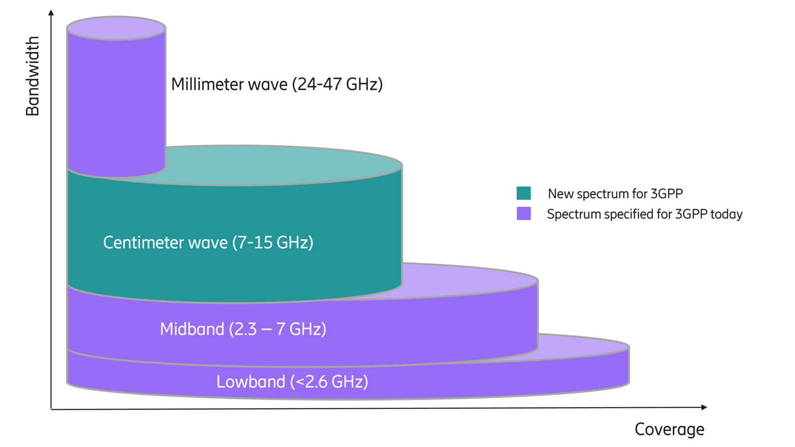
Figure 1: Candidate spectrum ranges for 6G, spanning existing FR1 and FR2 bands as well as new centimeter wave spectrum (7–15 GHz)
In addition to FR1 and FR2 spectrum, centimeter wave spectrum – particularly the lower part of the 7–15 GHz range – is emerging as a promising new band that has not previously been used for cellular communication. This spectrum can provide significant additional capacity for 6G and, when combined with massive MIMO and beamforming, may offer downlink coverage comparable to today’s mid-band deployments.
Despite these new opportunities, wide-area coverage will continue to rely heavily on FR1 spectrum. Unfortunately, very little unused spectrum remains in this range. As a result, 6G must be able to operate efficiently in spectrum that is already used by existing technologies. This is where 5G–6G spectrum sharing becomes essential. Fortunately, the ultra-lean design of 5G makes efficient sharing with 6G possible with very low overhead and complexity. These characteristics make MRSS a practical and efficient migration path from 5G to 6G networks, without requiring architecturally complex solutions such as dual connectivity.
Limited spectrum availability below 7 GHz, combined with long device lifecycles for many device types, also means that 5G and 6G will need to coexist for many years. MRSS solutions must therefore support robust and efficient spectrum sharing for at least a decade.
Dynamic spectrum sharing (DSS) played an important role during the migration from 4G to 5G. However, MRSS differs from DSS in a few important ways. Firstly, MRSS supports both FDD and TDD, reflecting the widespread use of both duplex modes in 5G, while DSS primarily focused on FDD. Secondly, MRSS achieves significantly lower overhead and higher efficiency, thanks to the ultra-lean design of 5G. This contrasts with 4G systems, which rely on many always-on signals.
In the following sections, we examine the requirements for MRSS and discuss technical mechanisms that enable efficient spectrum sharing between 5G, 6G and long-lived IoT technologies.
Scenarios and requirements
The limited amount of FR1 spectrum crucial for wide-area coverage leads to a key design principle: 6G should be able to share spectrum efficiently with 5G when required, without compromising performance in pure 6G deployments. The importance of FR1 for coverage is also the reason why 3GPP is primarily focusing on MRSS solutions for this frequency range. In FR2, the need for spectrum sharing is smaller. Extensive beamforming in these bands naturally provides spatial separation between users, reducing interference between technologies. Nevertheless, the solutions developed for FR1 can also be applied to FR2 when needed.
Efficient sharing between 5G and 6G implies that the resource sharing must be dynamic. Traffic in mobile networks is highly bursty and when there is no 5G traffic present the entire carrier should be available for 6G users – and vice versa. Achieving this requires tight scheduling coordination between the two systems on a millisecond timescale.
It is essential that the introduction of 6G in spectrum already used by 5G has minimal impact on existing networks. Configuration changes on the 5G side should ideally be avoided beyond normal scheduling behavior. For example, 5G user equipment (UE) should not detect or report 6G cells, since such reports could interfere with mobility procedures – 5G UE cannot connect to 6G cells. Similarly, any new 6G signals and channels must be effectively hidden from existing 5G UE using mechanisms already supported in deployed networks.
In addition to smartphones and other consumer devices, MRSS must also account for IoT devices with very long lifecycles – often 20 years or more. These devices typically rely on technologies derived from 4G and therefore introduce additional requirements for spectrum sharing solutions. Because IoT technologies use narrow bandwidths, a semi-static approach to spectrum sharing has been agreed within 3GPP RAN for coexistence with NB-IoT and eMTC.
Sharing between 5G and 6G
Efficient spectrum sharing requires minimizing interference between 5G and 6G transmissions. One important step is the decision to use the same Orthogonal Frequency-Division Multiplexing (OFDM) waveform and the same numerology in 6G as in 5G, with aligned subcarriers. This alignment was decided early in the 6G development process within 3GPP and simplifies coexistence between the two systems.
Dynamic scheduling, complemented by semi-statically configured reserved resources, can then enable efficient sharing of the carrier. Since both systems schedule data transmissions dynamically, sharing can largely be handled by the schedulers themselves without major specification impact. Resource-block alignment between the two technologies further enables fine-grained sharing while still allowing high-performance operation in pure 6G deployments. However, initial access procedures and Layer-1 control signaling are not dynamically scheduled and therefore require additional consideration during specification.
At a high level, 6G will resemble 5G in several respects. This raises the question of whether 6G should reuse certain 5G transmissions or define new ones. Reusing 5G signals could reduce overhead, since a single transmission might serve both systems. Defining new signals, on the other hand, allows greater design flexibility and avoids unnecessary constraints on the 6G system. As we noted earlier, not compromising 6G-only performance is a key design principle because we know that many carriers will eventually operate as pure 6G deployments. 6G design should therefore primarily focus on maximizing standalone performance and reuse of 5G signals should be considered on a case-by-case basis.
Another important aspect is the channel and synchronization raster, which determines how carriers are positioned in frequency and discovered in time. While these designs may evolve in 6G, they must remain compatible with 5G rasters to preserve MRSS efficiency.
MRSS itself is not expected to introduce new RF requirements for base stations or devices. In an MRSS deployment, a radio base station transmits both 5G and 6G signals within the same carrier, requiring consistent timing, numerology and frame structures. These characteristics are best viewed as properties of a multi-standard radio rather than MRSS-specific additions.
With this background, we can examine several key signals and channels and how they support MRSS.
Synchronization signal block
The Synchronization Signal Block (SSB) plays a central role in initial access and mobility measurements. To fully exploit the potential of 6G – for example improved energy efficiency – a 6G-specific SSB will be defined. Its exact time-frequency structure has not yet been finalized in 3GPP, but the transmission must remain invisible to 5G-only UEs. This can be achieved either by using unused 5G SSB transmission occasions or by ensuring that 5G transmissions are not scheduled on resources used by 6G SSBs, as shown in Figure 2.
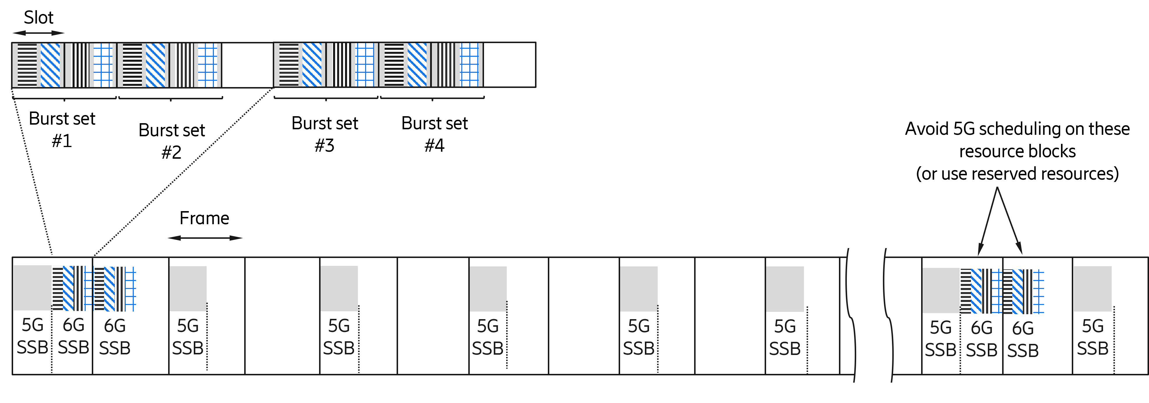
Figure 2: Example of 5G and 6G SSBs for a possible 6G design with repetition of multiple bursts
If 6G uses different synchronization sequences, 6G cells will naturally remain invisible to 5G-only UEs, which is desirable for mobility handling.
System Information Blocks (SIBs) are dynamically scheduled like regular data transmissions. As a result, the additional overhead from 6G SSBs and SIBs on an MRSS carrier can remain very small – well below one percent.
Random access
Random-access transmissions can be handled in a way that is similar to the process for SSB. The same time-frequency resources can be configured for both 5G and 6G random-access attempts, while the two systems are distinguished using different preambles. This also provides an early indication of whether the UE attempting to connect is a 5G or 6G device.
Physical downlink control channel
The Physical Downlink Control Channel (PDCCH) is used to schedule uplink and downlink transmissions. In 5G, PDCCH transmissions occur within configurable time-frequency regions known as control resource sets (CORESETs). Within each CORESET, a pseudo-random hashing function determines the exact location of PDCCH candidates.
6G is expected to follow similar principles, although the exact hashing function is still under discussion. Reusing the 5G hashing function could enable highly efficient coexistence, since transmitting a 6G PDCCH would be almost identical to transmitting a 5G PDCCH and would inherit existing collision-handling mechanisms. Alternatively, modifications to the hashing function could improve performance in pure 6G deployments, although this might slightly reduce MRSS efficiency. These trade-offs are currently being evaluated in 3GPP.
Figure 3 shows some examples of how 5G and 6G CORESETs can coexist. In the leftmost figure, the two CORESETs completely overlap, a suitable approach if the 5G and 6G hashing functions are identical (or sufficiently similar), while the rightmost figure illustrates non-overlapping CORESETs with no constraints on the 6G PDCCH hashing function. Partial overlapping CORESETs as shown in the middle figure is also possible; if 5G PDCCHs are allocated starting from the non-overlapping region of the CORESET collisions with 6G PDCCHs are avoided most of the time.

Figure 3: Possible configurations for 5G and 6G CORESETs, ranging from fully overlapping to separate control regions depending on design trade-offs
Other signals with relatively small impact may also require attention. Channel State Information Reference Signals (CSI-RS) are one example. If some 6G CSI-RS transmissions match the time-frequency footprint of their 5G counterparts, existing mechanisms can support MRSS in this area.
Sharing with NB-IoT and LTE-M
Apart from 6G-5G sharing, spectrum sharing must also consider 4G-derived IoT technologies such as NB-IoT and LTE-M. These devices often have lifecycles extending into the 2040s and typically operate in sub-GHz spectrum that will remain important for wide-area 6G coverage.
One option would be to statically partition the carrier between IoT and 6G services. However, this would lead to inefficient spectrum usage. For example, reserving 3 MHz of a 10 MHz carrier for IoT would leave only 7 MHz for 6G – even when IoT traffic is minimal.
A more efficient approach is illustrated in Figure 4. Here, 6G UEs are semi-statically configured with reserved resources corresponding to OFDM symbols used for mandatory cell-specific reference signals on the IoT carrier. This mechanism already exists in 5G and is known as FG 5-26.
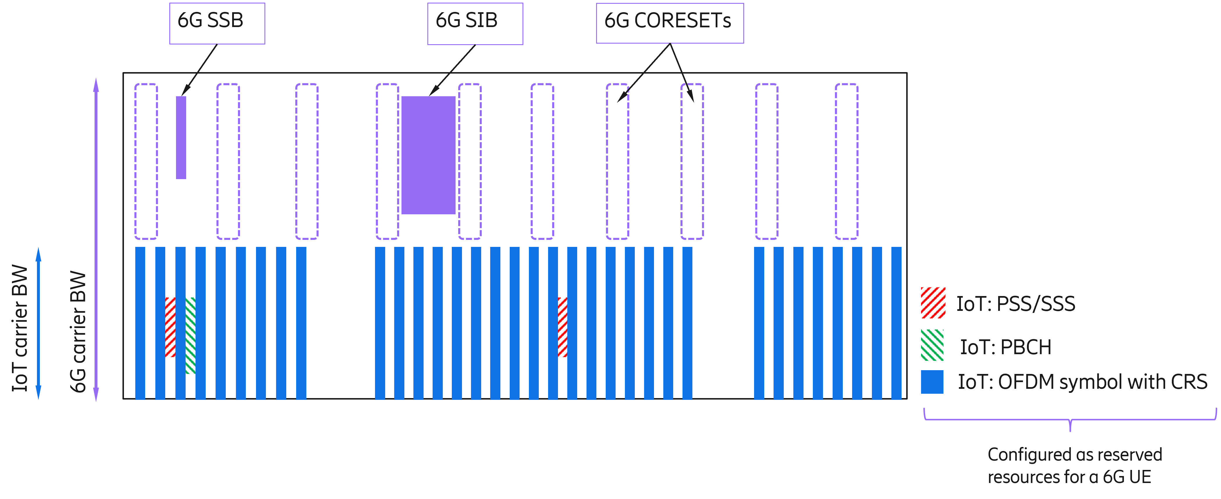
Figure 4: Example of efficient spectrum sharing between 6G and NB-IoT/LTE-M, where 6G avoids IoT reference signals through semi-static rate matching
When IoT traffic is absent, the 6G scheduler can use almost the entire carrier bandwidth, excluding only the reference-signal resources required by NB-IoT and LTE-M. Rate matching of the PDSCH avoids collisions with these signals, allowing 6G to use the remaining resources efficiently.
Conclusion
Multi-RAT spectrum sharing will be a key capability for the introduction of 6G networks. With limited new spectrum available below 7 GHz, efficient reuse of existing FR1 spectrum will be essential for delivering wide-area coverage and supporting continued traffic growth.
By aligning numerology, scheduling mechanisms and key signals between 5G and 6G, MRSS enables dynamic spectrum sharing with minimal overhead while preserving high performance in standalone 6G deployments.
At the same time, MRSS supports continued coexistence with long-lived IoT technologies such as NB-IoT and LTE-M, ensuring that existing deployments can continue to operate as networks evolve. In this way, MRSS provides a practical and scalable migration path from 5G to 6G while maximizing the long-term value of existing spectrum assets.