Extending 6G network-based sensing with UE assistance
- Wireless sensing is evolving beyond base stations to also include user equipment (UE) assistance for improving line-of-sight coverage and enabling richer measurements.
- We have explored the architecture of 6G network-based sensing when it’s augmented by UE assistance and conclude that it is beneficial to let the RAN be in control of the assisting UEs.
Senior Expert, Core network architecture
Expert, Network features and control architectures
Senior Expert, Core network architecture
Expert, Network features and control architectures
Senior Expert, Core network architecture
Expert, Network features and control architectures
Wireless sensing is a technology that enables a wireless system to acquire information about characteristics of the environment and/or objects within that environment. When sensing is integrated into a mobile communication system, it is known as Integrated Sensing and Communication (ISAC).
This blog post elaborates on an architecture that allows the mobile system to make use not only of base stations but also of UEs in a smooth way. Such UEs include stationary, operator-owned UEs, as well as mobile subscriber UEs.
Sensing in 5G and 6G
3GPP system-based sensing is currently being developed. In 5G, the sensing capability is introduced to the base stations (the gNBs), starting with mono-static sensing. Later, bi- and multi-static sensing modes could also be considered. The gNB-based sensing developed in 5G is controlled from the network, this is referred to as network-based sensing.
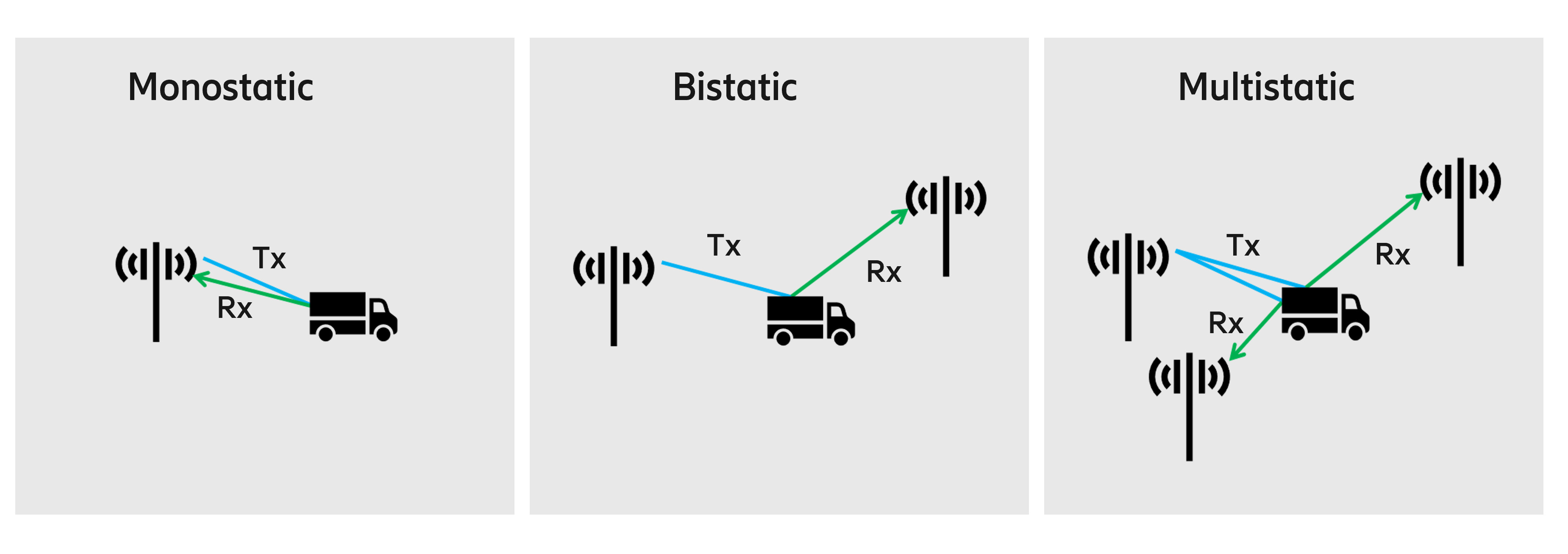
Figure 1: Sensing modes
For 6G, network-based sensing is expected to support additional sensing modes, where the sensing-capable base stations are complemented by UEs assisting the sensing measurements. This means that UEs can be in bi- or multi-static sensing modes with base stations. When the network is in control of sensing, this is called UE-assisted sensing.
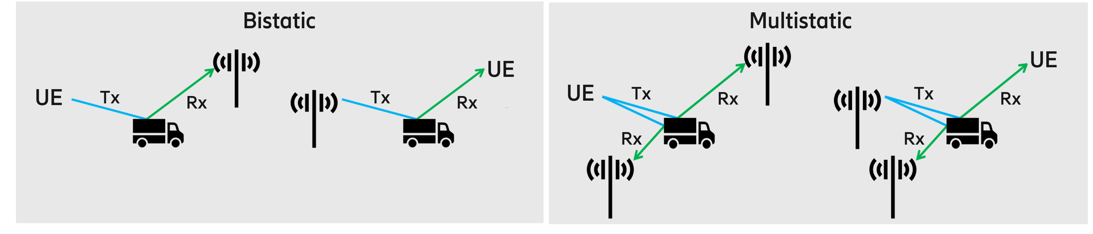
Figure 2: Sensing modes including assisting UEs
Having line-of-sight (LoS) between the transmitter/receiver in a base station and an object is challenging when it comes to ground targets (read more in the blog post Integrated Sensing and Communication). Simulations of city deployments done by Ericsson show that the LoS coverage for sensing can be as low as 10-15 percent. To improve the LoS coverage for ground targets, UE assisted sensing can be used.
Note that the industry also talks about UE-based sensing. This is when the UE is in control of sensing, in UE mono-static sensing, or possibly in collaboration with other UEs (UE-UE bi- or multi-static sensing). This blog post only discusses network-based sensing with UE assistance.
UE assistance architecture
The architecture of network-based sensing was described in the Ericsson Technology Review article, Sensing in 6G: Use cases and architecture. In this architecture, the sensing client requests the sensing service from the network, for example in a certain area. The network authorizes the request, applies relevant policies, for example area restrictions, and creates a workflow for the requested sensing service. Based on the workflow, the Core Network (CN) requests the RAN to perform sensing measurements in a certain target sensing area. The RAN maps this target sensing area into one or more sensing measurements, where each sensing measurement uses a set of base stations that are likely to have LoS of the same geographical area. Hence, for geographically larger target sensing areas, the RAN will have to break the request down into multiple measurements, each executed using a set of base stations in any of the above-mentioned sensing modes (as decided by the RAN).
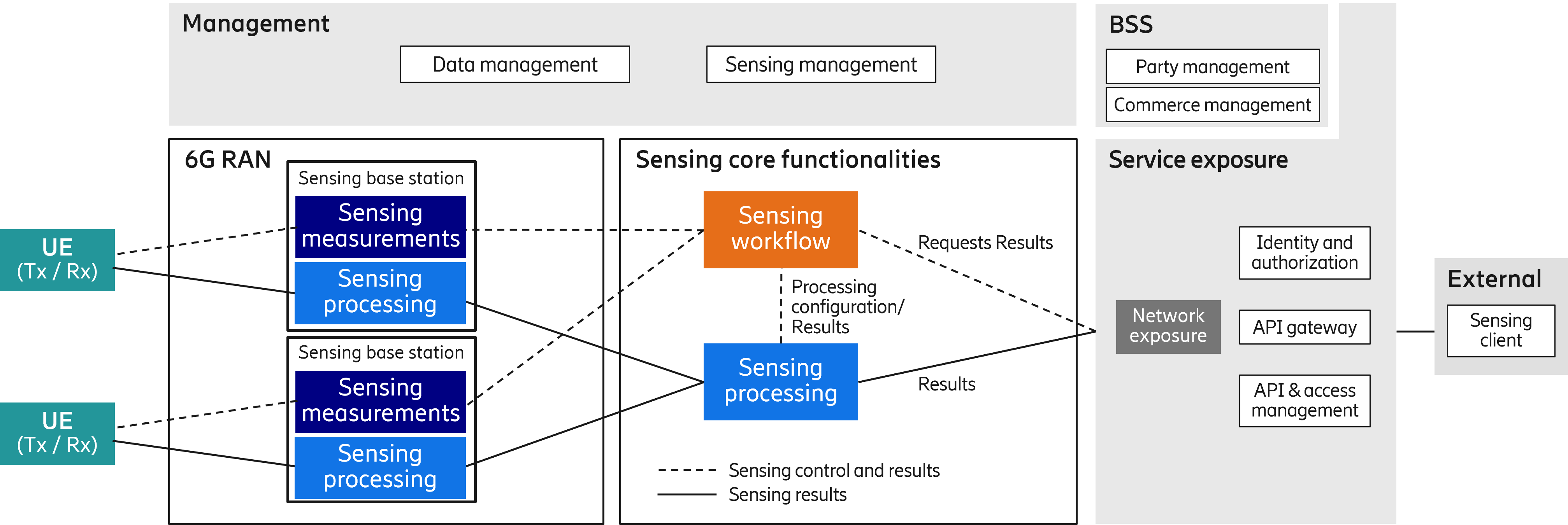
Figure 3: End-to-end sensing architecture, extended with assisting UEs
Assisting UEs are treated as just another type of sensing-capable entity, in addition to base stations. They can participate in sensing measurements and be selected for either transmit (Tx) or receive (Rx) roles (or both), when the network decides it is beneficial to enlist UE assistance. The selection of UEs to assist, and how to assign the Tx and Rx roles is a radio resource decision that is best taken by the 6G RAN. This is because the 6G RAN, rather than the CN or any UE, has sufficient knowledge and control of the radio resources to make efficient use of them. Also, only the 6G RAN knows (and should know) all the details of the base stations to involve them in a sensing measurement. As a result, no change is required in the functional split between the RAN and CN when assisting UEs are introduced.
Configuring and coordinating assisting UEs
To communicate with assisting UEs, the 6G RAN can simply use the serving base station of the assisting UE. Both transmitting and receiving assisting UEs must be configured with the exact resources such as time, frequency, code, and patterns of the measurement, while receiving assisting UEs must also be capable of delivering measurement data to the network for fusion. The 6G RAN is both the source of the sensing configuration sent to an assisting UE and the destination for sensing measurements taken by an assisting UE, where fusion with other receiver’s data takes place. Therefore, sensing-related communication with assisting UEs requires only minimal involvement from the communication CN. This fact enables separating the communication and sensing functions in the core even in the presence of assisting UEs. The communication CN only needs to deliver information about sensing such as whether assistance is allowed for this UE at this location or not.
Discovering and managing assisting UEs
To involve UEs in a sensing measurement, the 6G RAN must be aware of the UEs and know their rudimentary location. Consequently, to involve UEs, the 6G RAN must keep track of UEs that can be used for sensing measurements. This is easy for operator-deployed stationary UEs, whose location is stable. Mobile UEs, on the other hand, may roam freely and may only be relevant for a particular sensing area for a limited time. The 6G RAN (the serving base stations) can easily maintain a list of available assisting UEs that are in connected mode.
Potential assisting UEs that are in idle mode or inactive state must be actively discovered and brought into connected mode before being involved in a sensing measurement, if there are no known suitable assisting UEs in the area. Such discovery may be made by broadcasting a request (a form of paging) for a certain capability in a certain location (rather than a certain identity). In such a procedure, the RAN would ask idle or inactive UEs to wake up if they have the requested sensing capability. The network can then roughly estimate the position of UEs checking in and select one or more for the sensing measurement. If a certain area has a lot of mobile UEs and several sensing measurements, the network can actively maintain a rotating set of UEs in connected mode to reduce the latency for activating sensing measurements.
For a UE to be useful for a sensing measurement, in addition to being in a suitable location, it also needs to be capable, willing (user control), and allowed (operator control) to support sensing. The sensing capability is typically signaled to the network from the UE itself. The willingness to participate in sensing may be influenced by multiple actors: the actual user, the owner of the device and/or subscription (such as employer) and maybe more. Consent from these actors may come directly from the device or through an operator-based portal, or some other means. Whether and how the UE is allowed to assist the sensing measurement (operator control) is based on information in subscription data. This information propagates to the 6G RAN whenever the UE goes from idle to connected mode, that is, when establishing a UE context in the 6G RAN. Consequently, the 6G RAN has the necessary information as well as a rough location for each UE under its control and can hence decide whether or not to use a certain UE to assist a sensing measurement.
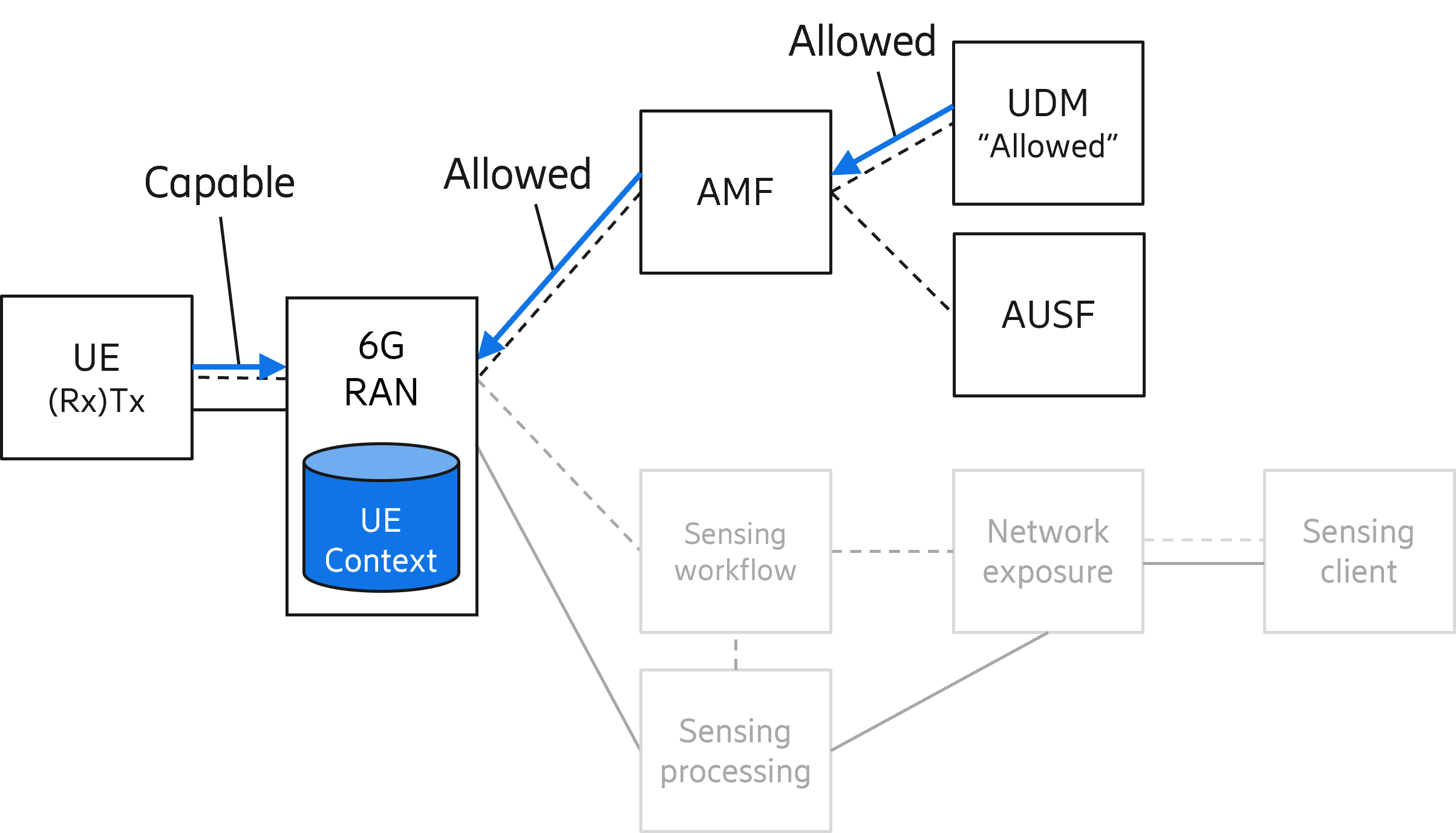
Figure 4: Information flow regarding UE sensing capability and operator permission
Key take-aways
Sensing that involves base stations and operator spectrum is naturally controlled by the 6G RAN. In this blog post, we argue that this remains the case even if UEs are assisting in network-based sensing. With assisting UE control residing in the RAN, only minimal involvement is needed from the communication CN. Finally, we discuss a possible new broadcast request to discover UEs that could potentially assist in a sensing measurement.