5G positioning: What you need to know
Senior Researcher Radio
Senior Researcher, Radio
Senior Researcher, Radio
Expert in RAN Automation and Positioning
Senior Researcher Radio
Senior Researcher, Radio
Senior Researcher, Radio
Expert in RAN Automation and Positioning
Senior Researcher Radio
Senior Researcher, Radio
Senior Researcher, Radio
Expert in RAN Automation and Positioning
5G positioning is a natural component in many anticipated 5G industrial use cases and verticals such as logistics, smart factories, autonomous vessels and vehicles, localized sensing, digital twins, augmented and virtual reality.
The history of positioning in cellular networks dates back to the mid-nineties when it was originally introduced to meet regulatory requirements of emergency call positioning. Today, with Industry 4.0, 5G positioning use cases come with a plethora of performance requirements in terms of accuracy, latency, availability, reliability, and more.
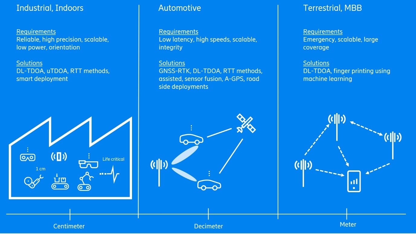
Figure 1: Requirements and specific solutions of 5G use cases with possible 5G positioning accuracy range
Some of those use cases can be seen in the figure above, together with their typical requirements, possible positioning methods and the expected accuracies. As you can see, accuracy requirements can range from meters to centimeters depending on the use case.
5G positioning and use cases
Mobile broadband (MBB)
Consumers with a cellular phone will also experience accurate positioning through 5G. It is expected that with some reasonable density of deployments in urban areas, 10 meters (m) positioning accuracy can be achieved. For pedestrians under a clear sky and with access to Global Navigation Satellite Systems (GNSS) such as GPS, positioning with a fusion of 5G and GNSS can be better than positioning with GNSS alone.
5G indoor positioning
Positioning of users and devices across general indoor environments, such as offices, shops, logistics, etc., was a focus area of 3GPP Release 16. The introduced features are also applicable in industrial scenarios, with possible enhancements being considered in Release 17.
Vehicular to everything (V2X)
Vehicles on roads can be better positioned using a combination of GNSS and 5G positioning. The network relaying the GNSS assistance information also enables very accurate GNSS-RTK based positioning for vehicular scenarios. Street level millimeter wave (mmWave) base station deployments will play a crucial role in providing on-road very accurate positioning. Highly accurate vehicular positioning will be important for autonomous driving.
5G drone localization
Drones are expected to be widely deployed and more visible in times to come. In the future, drones can even be deployed as moving base stations and must have the ability to localize themselves for positioning. Drones will often have line-of-sight between each other and to the base stations on ground, which is a benefit. It is expected that a fusion of GNSS and 5G can provide decimeter level positioning accuracies in such scenarios, making it easier to maneuver drones. One example where drone localization would be necessary is in the assistance of first responders on a disaster site. Drones could be used as temporary base station deployed when the disaster site network is down and assist in keeping track of the responders’ locations as well as controlling other drones.
3GPP evolution to 5G positioning
5G new radio (NR) was initially introduced as a non-standalone extension to 4G. Initially, in 3GPP Release 15, 5G device positioning was enabled by an overlay 4G network, providing 4G positioning reference signals to measure on. To leverage on the multiple sensors available in today’s devices, the support for technologies independent of 3GPP radio access technologies (RAT), such as GNSS, Bluetooth, barometric pressure, WiFi signal strength, inertial sensors, and many more, was naturally extended to apply to 4G and 5G. Dedicated 5G positioning reference signals, measurements and procedures were introduced in 3GPP Release 16.
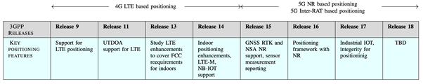
Table 1: The evolution of positioning support in 3GPP standardization
Key features of 5G NR positioning
5G NR provides a few enhanced parameters for positioning accuracy estimation than previous mobile generations, particularly with regards to time- and angle-based positioning methods. Below, we list a few key observations on these parameters.
- The delay error variance decreases in the order of the square of the bandwidth as the bandwidth increases. However, the angle variance is completely independent of the bandwidth. NR provides significant bandwidth improvement over LTE; while LTE provides a maximum of 20 MHz, NR provides up to 100 MHz in frequency range 1 and 400 MHz in frequency range 2.
- Received power is inversely proportional to all estimate variances. In NR, received power can be increased by beamforming. This is especially more important for numerologies with higher subcarrier spacings.
- NR provides five different choices for subcarrier spacing: 15 kHz, 30 kHz, 60 kHz, 120 kHz and 240 kHz. The subcarrier-spacing is a bit peculiar since it gives a linear increase to the angle variances, while at the same time giving only a linear decrease to the delay variance. This effect is derived from the noise variance increasing linearly with the subcarrier spacing. A natural way to counter this is to increase the RX power.
- Different antenna patterns, in terms of spacings and number of polarizations in relation to rows and columns in antenna array etc. do not affect the delay variance, but rather only the total number of antenna elements in the array matter. For the angle estimates, the variance is proportional to the inverse square of the antenna spacing. Furthermore, the number of rows and columns respectively of the antenna array gives a cubic decrease in the angle estimate variances. Typically, NR equipment carries a larger number of antennas.
5G positioning in 3GPP Release 16
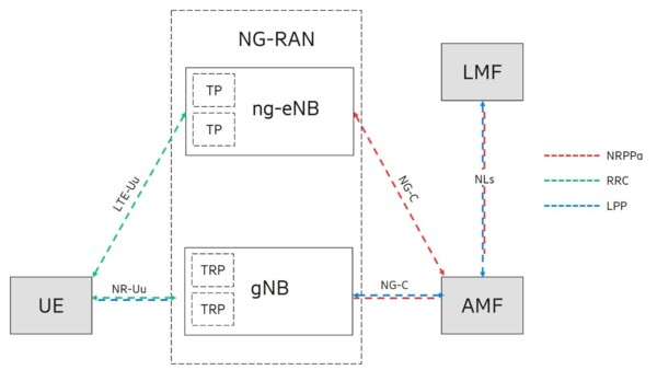
Figure 2: 5G architecture supporting positioning
The new entity, location management function (LMF), is central in the 5G positioning architecture. The LMF receives measurements and assistance information from the next generation radio access network (NG-RAN) and the mobile device, otherwise known as the user equipment (UE), via the access and mobility management function (AMF) over the NLs interface to compute the position of the UE. Due to the new next generation interface between the NG-RAN and the core network, a new NR positioning protocol A (NRPPa) protocol was introduced to carry the positioning information between NG-RAN and LMF over the next generation control plane interface (NG-C). These additions in the 5G architecture provide the framework for positioning in 5G. The LMF configures the UE using the LTE positioning protocol (LPP) via AMF. The NG RAN configures the UE using radio resource control (RRC) protocol over LTE-Uu and NR-Uu.
To enable more accurate positioning measurements than LTE, new reference signals were added to the NR specifications. These signals are the positioning reference signal (NR PRS) in the downlink and the sounding reference signal (SRS) for positioning in the uplink. The downlink positioning reference signal (PRS) is the main reference signal supporting downlink-based positioning methods. Although other signals can be used, PRS is specifically designed to deliver the highest possible levels of accuracy, coverage, and interference avoidance and suppression. To design an efficient PRS, special care was taken to give the signal a large delay spread range, since it must be received from potentially distant neighboring base stations for position estimation. This is achieved by covering the whole NR bandwidth and transmitting PRS over multiple symbols that can be aggregated to accumulate power. The density of subcarrier occupied in a given PRS symbol is referred to as the comb size. There are several configurable comb-based PRS patterns for comb-2,4,6 and 12 suitable for different scenarios serving different use cases. The pattern shown in the figure corresponds to comb-6 with 3 base stations multiplexed over one slot duration. For comb-N PRS, N symbols can be combined to cover all the subcarriers in the frequency domain. Each base station can then transmit in different sets of subcarriers to avoid interference. Since several base stations can transmit at the same time without interfering with each other, this solution is also latency efficient. Moreover, it is possible to mute the PRS signal from one or more base stations at a given time according to a muting pattern, further lowering the potential interference. For use cases with higher transmission loss (for example, in macro cell deployments) the PRS can be also configured to be repeated to improve hearability.
An example PRS with three base stations is shown in Figure 3 (a) below.
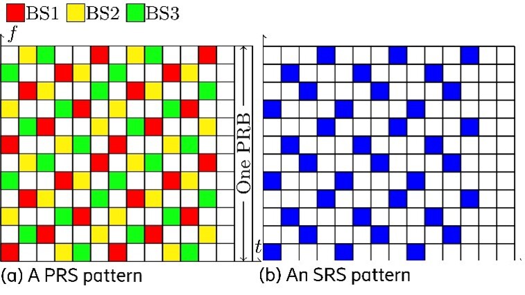
Figure 3: Reference signals for positioning. Shown are one configuration each of DL-PRS and UL-SRS.
In the uplink direction, 3GPP introduced the SRS for positioning in 3GPP Release 16. This new signal resolves two aspects specific to positioning. Since positioning involves measurements from multiple receiving base stations, the new signal must have enough range to reach not only the serving base station to which the UE is connected, but also the neighboring base stations involved in the positioning process. The SRS is also designed to cover the full bandwidth, where the resource elements are spread across the different symbols so as to cover all subcarriers. Therefore, SRS is also designed with a comb-based pattern similar to the PRS. UEs can be multiplexed over the same transmitting symbol by assigning different comb patterns. To minimize interference, the UE can be configured with different SRS instances, each with independent power control loops. This allows SRS pointed at neighbor cells to have better hearability and keeps the interference low in the serving cell. An example SRS by a UE is shown in Fig.3 (b).
Different positioning methods may require different measurements. 3GPP has standardized power, angular and time measurement support for the PRS. A beam sweep across a resource set of PRS is illustrated in Figure 4 below.
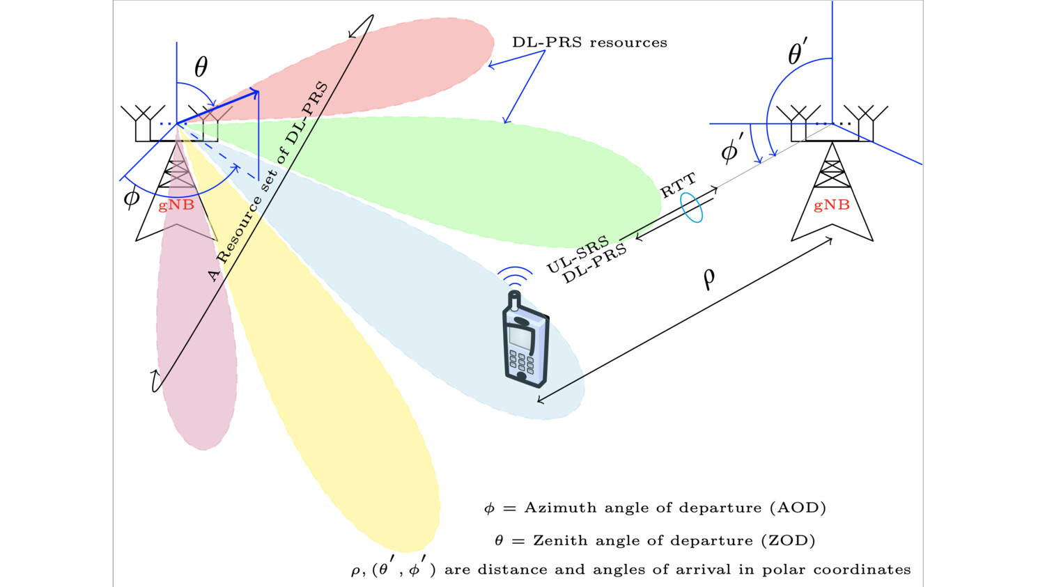
Illustration depicting beamforming, multi-antenna aspects in 5G positioning
Each beam can be seen as a resource. Measurements are collected across one or multiple resource and resource sets. Beamforming improves the signal to noise ratio (SNR) due to beamforming gain besides providing UE location information in terms of the angle of departure (AOD) based on the beam ID accessed by the UE, while a large number of antennas at the receiver in the uplink enables fine angle of arrival (AOA) measurements with NR. Many of these measurements are standardized to enable variety of positioning methods. Since 4G LTE, mobile networks have supported observed time difference of arrival (OTDOA), uplink time difference of arrival (UL-TDOA) and positioning methods based on power measurements. In 5G, the list of supported methods is extended to include round trip time (RTT) and angle-based positioning. The inclusion of new positioning methods and enhancements of existing positioning methods enables high accuracy positioning for several use cases in 5G.
Open and interoperable 5G positioning in the recent 3GPP release enables appropriate positioning for many commercial use cases. Work is ongoing with advanced algorithms, adaptions to specific use cases and identification of relevant enhancements.
Learn more
- Find out how 5G and other technologies are turning mobile networks into platforms for innovation.
- Find out how 5G NR for public safety could save lives.
- Learn more about LTE Positioning and real-time kinematic in this post from 2018.
- Learn more about mobile positioning systems for drone traffic management in this post from 2017.