The cell edge problem solved? User-focused uplink power control using reinforcement learning
Senior AI Technical Product Manager
Senior Data Scientist at Ericsson R&D
Director – Data Science
Senior Al Technical Product Manager
Senior AI Technical Product Manager
Senior Data Scientist at Ericsson R&D
Director – Data Science
Senior Al Technical Product Manager
Senior AI Technical Product Manager
Senior Data Scientist at Ericsson R&D
Director – Data Science
Senior Al Technical Product Manager
Some of the most sought 5G use cases are massive and critical Internet of Things (IoT), enhanced mobile broadband (eMBB) and ultra-reliable low-latency communication (URLLC), as well as massive Machine-Type Communication (mMTC). All these use cases have varying performance requirements e.g., latency lower than 5 milliseconds (ms), remarkably high throughput and battery life that can reach days and even months. In such complex scenarios, fine-grained tuning of network configuration may be necessary to maximize quality of service (QoS) for the receiving application or use case.
Uplink power control (UL-PC) is critical for a good balance of coverage and capacity in the uplink path. But a non-coherent power control may cause sub-par performance in scenarios where there is a high volume of cell edge user equipment (UE), that is to say users and devices located at the very edge of the cell far from the base station. This is known as the ‘cell edge problem’ and may lead to high interference, high setup failures, call drops and lower throughput. Intelligent UL-PC using RL is one way to solve this problem and can become a crucial mechanism in order for service providers to fulfill both Service Level Agreements (SLAs) and QoS requirements for use cases that demand e.g., high data rates or longer battery life.
In this blog, we discuss the challenges faced by power limited UEs caused by incoherent power control command. We discuss how RL can help to provide a spatial and temporally correlated power control mechanism by leveraging the data reported from UEs. Our specific focus is on closed-loop power control in which Transmit Power Control (TPC) commands are sent by the gNB/eNB.
In general, UL-PC indicates an increase or decrease in the transmit power of the UE. An increase of power may be required to meet the signal-to-noise ratio (SNR) or block error rate (BER) constraints at the gNB (base station or eNB). A decrease is aimed to minimize co-channel interference of the 5G system.
Existing uplink power control: The challenges
UL-PC determines the power for associated UL channels. It can be classified as an open and closed PC loop. In open-loop PC, the UE determines the UL transmission power. Open loop power is based on the expected receiving power indicated by the network, along with the path loss measurement from the downlink (DL) reference signal at the UE side.
In closed-loop PC, explicit power-control commands are sent by the network based on previous measurements of the received uplink power. 5G NR has the capability for beam-based PC as an extension of LTE. Still baseline PC under closed loop remains the same. Consideration of various numerologies and beams has been embedded in the baseline mechanism.
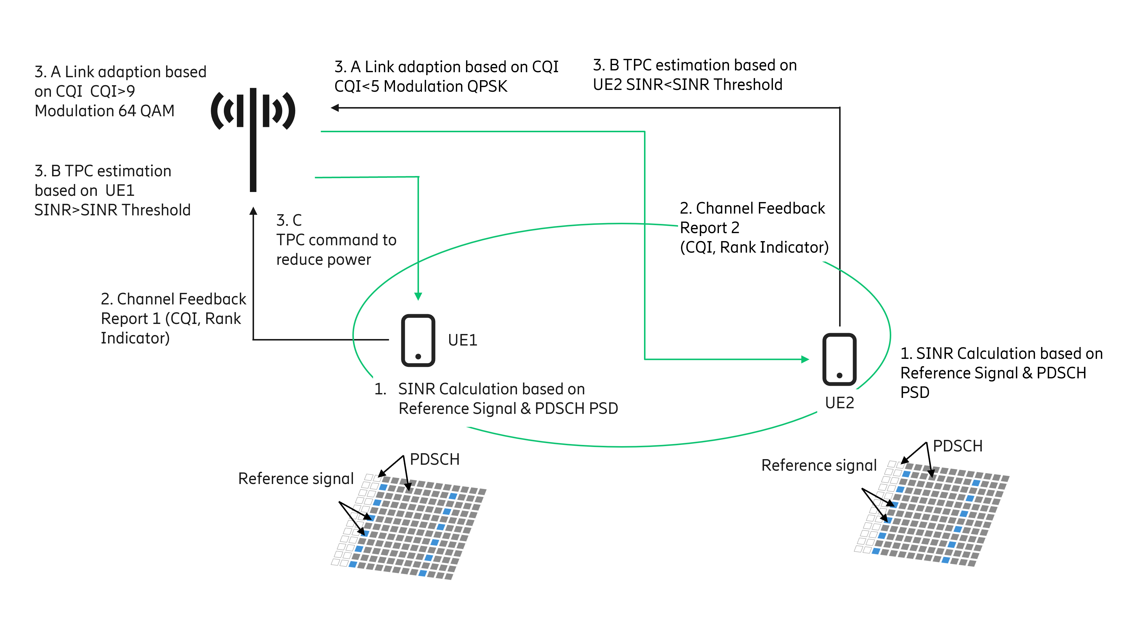
Figure 1: An overview of the current workflow for UL-PC.
The conventional workflow, shown in Figure 1, would involve the following steps:
- UEs (e.g., UE1, UE2) estimate SINR based on the Power Spectral Density (PSD) of the DL Reference Signals (RSs) and PSD offset between PDSCH and RSs.
- The SINR is converted to Channel Quality Indicator (CQI) and reported to the node in the Channel Feedback Report (CFR) having CQI and rank indicator. In Figure 1, two-channel feedback reports corresponding to UE1 and UE2 are shown.
- The CQI indicates the radio quality and is used by the link adaptation function.
- Based on CQI, the modulation scheme is determined which helps to select the suitable transport block size. For example, UE1 reported CQI is >9, which indicates good radio conditions, hence a higher order modulation scheme e.g., 64QAM can be selected. Similarly, UE2 reported CQI is <5 (indicating poor radio conditions), hence lower modulation such as QPSK can be selected.
- Reported SINR is considered to determine the PC action. In Figure 1, UE1 reported SINR is higher than the threshold, while UE2 reported SINR is lower than the threshold.
- The base station will send the Transmit Power Control (TPC) command to UEs as per the output of step 3B. E.g., UE1 is directed to reduce the power while UE2 is asked to increase the power.
UL channels PUSCH (physical uplink shared channel), PUCCH (physical uplink control channel) and SRS (sounding reference signal) largely follow similar baseline methods as specified in 3GPP TS 38.213. In the baseline method, there are certain parameters carried either by system information (or as the physical downlink control channel information) such as fractional path loss compensation, the number of resource blocks assigned and power control command.
The PC commands are carried in the TPC field within UL scheduling grants (DCI (Downlink control information) formats 0_0 and 0_1). PC commands can also be carried jointly to multiple devices by means of DCI format 2_2. Each PC command consists of two bits corresponding to four different update steps (-1 dB, 0 dB, +1 dB and +3 dB).
The UEs which are in poor radio conditions, such as at the cell edge, will be asked to increase the power, while simultaneously UEs which are in good radio conditions and meeting SINR will be asked to reduce the power. Power reduction by UEs can help reduce the overall interference and required power level to successfully communicate with the base station. The impact of power reduction on the system may vary depending on the relevant UEs ratio. However, asking all SINR violating UEs to increase the power without considering the impact on their Power Headroom Report (PHR) and interference in the system may have an undesirable impact on system performance. UEs in power limited states will not be able to increase their power further to overcome the interference. The interference could be a result of an increase of power of other UEs and may lead to degraded QoS for power limited UEs, meaning that they may encounter lower throughput, higher call drops and access failures.
Machine- and reinforcement learning models for efficient UL power control
A view of the workflow incorporating RL is shown in Figure 2. The RL method can be leveraged for TPC command identification to suit the needs of the dynamic radio environment.
In the RL setup, the base station (gNB/eNB) hosting the ML solution can act as an “agent” while remaining components, such as UEs or other base stations, form the “environment”. The RL approach involves determining a “state”, “action” and an associated “reward”. In this case, the UE power level forms the “state”, TPC command would be the “action”, and the “reward” function may include computation of network performance parameters across cells. The basic idea is that “actions” performed by an “agent” to change the “state” of the “environment” are associated with “rewards” that determine subsequent action(s). Actions that result in an improvement in network performance parameters are associated with positive rewards, while others are penalized to avoid their execution in future state(s). This results in learning an optimal PC mechanism that can cater to various application-specific requirements. A suitable RL approach may be chosen based on the requirements.
Now let’s briefly discuss the workings of such approaches. UEs associated with cells may be classified into sets that execute specified PC commands, based on specific criteria associated with performance requirements. This classification may be based on factors such as location, PHR, Buffer Status Report (BSR), interference observed by UE, or parameters such as Reference Signal Received Power (RSRP) or SNR. The base station PC commands are executed by UEs and reported back to obtain the next set of actions. These actions can impact the network performance, including aspects like interference, throughput, among others. The agent (hosted in base station i.e., gNB/eNB) determines rewards associated with these actions by using suitable cost function(s) and sends the subsequent set of commands to be executed by the UEs. Various approaches have been proposed in the literature that have gained popularity, such as those based on multi-agent systems, fractional power control, closed loop power control and deep RL (eliminates lookup table overhead but incurs cost of deep network training).
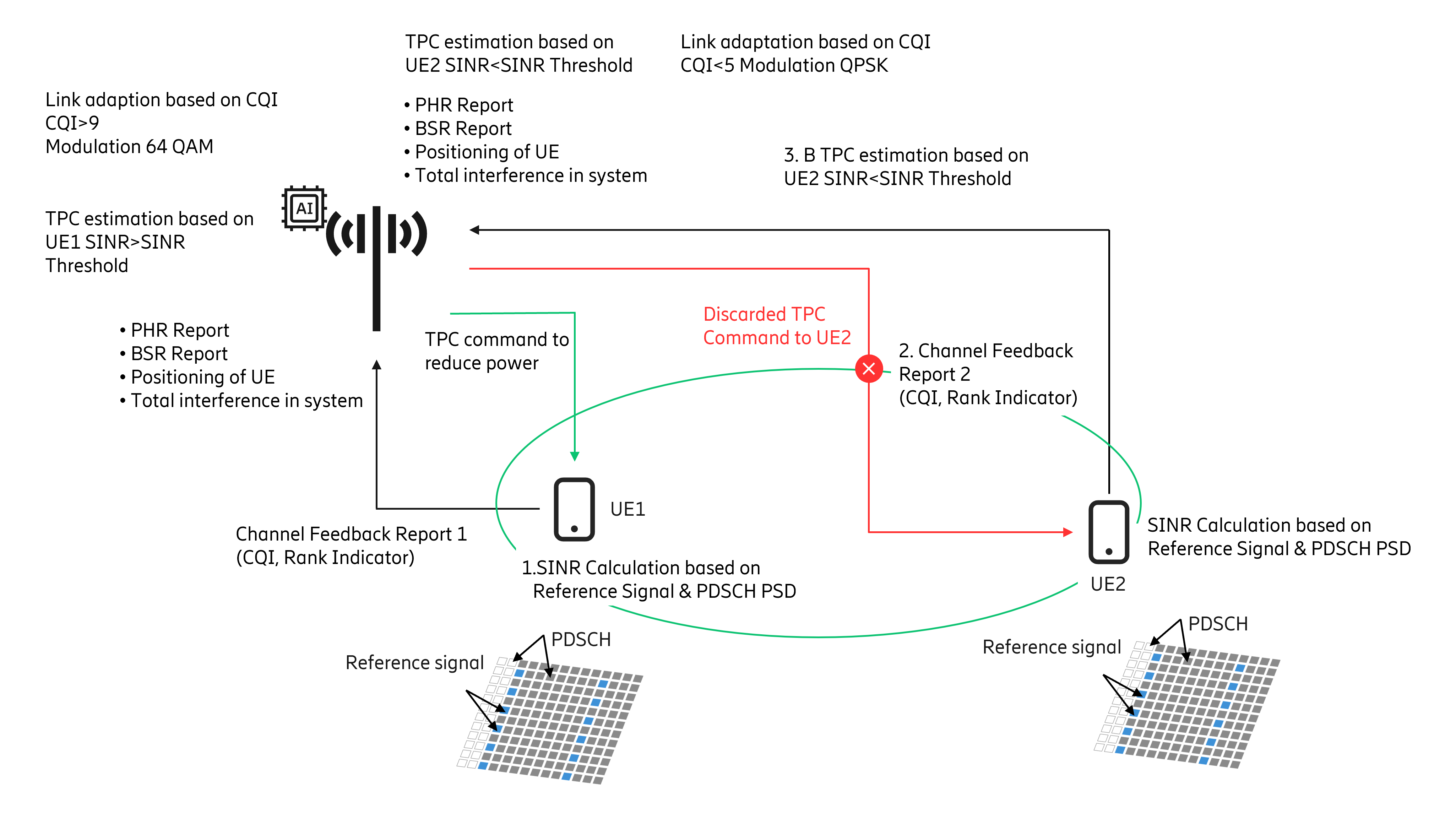
Figure 2: The workflow for ML/RL based UL power control.
ML/RL-based uplink power control: How it works
- UEs report the Channel Feedback Report (CFR). Based on reported CFR, the base station will determine the SINR. If the SINR conditions breach the threshold, then the base station will initiate the RL agent.
- The agent will have information such as previously reported PHR, BSR, positioning of UEs, total interference level of system and TPC commands’ decision.
- Based on this feature set, the agent will identify a set of UEs which will be asked to increase the power level.
- A point to note is, unlike the current mechanism where all UEs are signaled to increase their power, only a subset of UEs is asked to increase their power level.
- Based on the resultant of this power increase of the targeted UE subset, the agent will determine the reward function. This may use any of the approaches described previously.
- The iteration(s) will continue for a separate set of UEs. The subset formation will be based on PHR level, BSR level, and UE positioning.
- UEs positioned at various locations will be clustered in a way that different rewards can be estimated for different groupings.
- Based on reward comparison an optimal mix of power increase command with an optimal mix of UE subset (UE positioning) will be identified to increase the power in a way that interference is minimized in the cell.
- If UEs do not fall into the optimal subset during TPC command cycle, then such UEs will not be sent the power increase command [TPC=0 dB] and will be picked in the next cycle.
Conclusions
ML/RL based UL-PC can enable the system to learn the optimal mix of PC commands. Tuned UL-PC can help suit different UEs needs and can enhance UL throughput while keeping interference in check. This also results in better network energy efficiency and improved UE battery life.
Learn more
Find out how advanced machine learning techniques in combination with deep network knowledge is helping CSPs to balance energy savings, network performance and customer experience requirements.
Learn about the basic principles of reinforcement learning in future telecom networks.
Explore 5G