








Solving the uplink challenge in 6G
-
AI apps, drones, robots and XR glasses are flipping the network traffic model. AI traffic alone is forecast to make uplink volumes three times higher by 2031.
-
In this post, we explain the 6G technologies Ericsson is driving – in devices, in the radio interface and at the base station – that boost uplink coverage and capacity, with gains that can add up.

Senior Researcher, Radio access network (RAN) standardization

Principal Researcher, Radio Access Network standardization

Senior Researcher, Radio access network (RAN) standardization
Senior Researcher, Radio access network (RAN) standardization
Principal Researcher, Radio Access Network standardization
Senior Researcher, Radio access network (RAN) standardization
Senior Researcher, Radio access network (RAN) standardization
Principal Researcher, Radio Access Network standardization
Senior Researcher, Radio access network (RAN) standardization
Today’s mobile networks mostly carry downlink traffic, from the network to the user. In Ericsson’s measurements in a sample of networks, uplink traffic – from the user to the network – averaged only about 8 percent of total traffic volume.
This is changing fast, though. As our colleagues described in a recent post that explains how AI is flipping the network traffic model, AI-native apps, autonomous systems such as drones, robots and vehicles, and AR/VR/XR devices are driving a rapid rise in uplink demand. The June 2026 Ericsson Mobility Report forecasts, based on traffic scenario modeling, that additional AI traffic alone will make uplink volumes three times higher in 2031 than in 2025.
As we move toward 6G, it will be essential to improve real-world uplink performance.
Why uplink performance is limited today
Uplink performance is held back in two main ways, depending on where a user is in the cell (see Figure 1):
1. Coverage: Devices transmit at much lower power than base stations, which makes the outer cell region coverage constrained – typically the main limit for the uplink. Moreover, most users are indoors and face coverage issues due to worsened signal propagation conditions compared to outdoors.
2. Capacity: As uplink traffic and the number of users grow, the available uplink resources fill up. This makes the inner cell region (i.e., closer to the base station), typically featuring higher data rate uplink, capacity constrained.
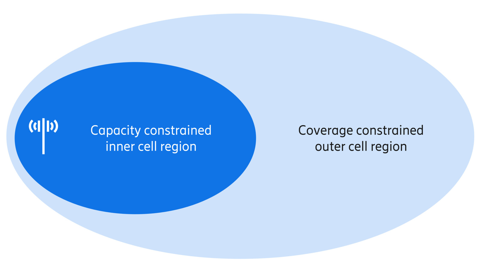
Figure 1: Capacity constrained inner cell region and coverage constrained outer cell region
How these limits play out also depends on how the spectrum is used:
- In frequency division duplexing (FDD), uplink and downlink use separate bands. The relatively narrow FDD bands can fill up faster than TDD bands, so uplink capacity and throughput can become a bottleneck.
- In time division duplexing (TDD), uplink and downlink share a band and take turns. Higher frequencies with greater path loss, and downlink-heavy time patterns that leave few chances to transmit, weaken uplink coverage and latency.
6G therefore needs to improve the uplink in both FDD and TDD, and throughout the cell – not just at the cell edge. It also needs to serve many kinds of devices, from smartphones to fixed wireless access (FWA) equipment and smart glasses.
Overview of uplink improvement technologies for 6G
Uplink improvement technologies for 6G fall into three groups:
1. Device improvements – better waveforms, higher transmit power and improved antennas in phones and other devices.
2. Feature improvements – new functions in the radio interface between device and network, such as protocols and signaling.
3. Base station improvements – network-side upgrades that work regardless of the device.
Device and feature improvements are easiest to introduce at a generational shift, such as from 5G to 6G, when device makers update their hardware and a new radio interface is defined. Base station improvements depend less on the generation.
The table below shows the gain or performance improvement potential of each technology, based on Ericsson evaluations. Many of them can be used together and their gains can add up.
1. Device improvements
| Technology | FDD | TDD | Inner cell region (capacity) | Outer cell region (coverage) |
| Multi-stream DFT-s-OFDM | ✓ | ✓ | 20% | 80% |
| FDSS | ✓ | ✓ | - | >25% |
| Higher-power devices (HPUE) | ✓ | ✓ | 45% | 145% |
| Improved PA design (power boost, less backoff) | ✓ | ✓ | 25% | 45% |
| FWA: 4 to 8 coherent transmit antennas | ✓ | 30% | - | |
| FWA: 1024 QAM | ✓ | >10% | - |
2. Feature improvements
| Technology | FDD | TDD | Inner cell region (capacity) | Outer cell region (coverage) |
| Uplink/downlink decoupling | ✓ | ✓ | - | 3x (at low load) |
| Advanced base station receivers, including AI | ✓ | ✓ | - | 80% |
| Long uplink scheduling (long PUSCH) | ✓ | - | 80% |
3. Base station improvements
| Technology | FDD | TDD | Inner cell region (capacity) | Outer cell region (coverage) |
| Mid-band FDD antennas: 4R to 32R | ✓ | 25% | 50% | |
| Low-band FDD antennas: 2R to 8R | ✓ | - | 200% |
Inner cell region: for example, median or mean throughput gain. Outer cell region: for example, cell-edge throughput gain. A dash (–) means that region is not relevant for that technology.
How each technology improves 6G uplink performance
Below, we look at each technology in turn: what it does, why it helps and what our evaluations show. The technologies are grouped according to where the bulk of the improvement happens – in the device, in the radio interface or at the base station.
1. Device improvements
Uplink performance depends heavily on the device, which transmits at much lower power than a base station. The four technologies below – more efficient waveforms, higher-power devices, improved power amplifiers and FWA improvements – help devices transmit with more power or make better use of the power they have.
More efficient uplink waveforms (DFT-s-OFDM and FDSS) – FDD and TDD
New waveform features will help devices send more data, especially where coverage is weak. A key example of Ericsson’s leadership in 6G standardization is the extension of the DFT-s-OFDM (discrete Fourier transform spread orthogonal frequency-division multiplexing) waveform from single-stream uplink in 5G to multi-stream uplink in 6G. DFT-s-OFDM lets devices transmit at higher average power without raising their peak power, which would translate into significantly better uplink performance across the whole cell.
Our evaluations show that multi-stream DFT-s-OFDM can give up to 80 percent higher cell-edge throughput and up to 20 percent higher median throughput.
A related technique, frequency-domain spectral shaping (FDSS), filters the transmitted signal so that the device can also transmit at higher average power within the same peak limit. Most of the gain comes from transparent FDSS, where the receiver doesn’t need to know the filter: up to 1 dB better coverage, or at least 25 percent higher throughput, compared with no FDSS.
Higher-power devices (HPUE) – FDD and TDD
Letting devices transmit at higher power is a straightforward way to improve the uplink. Raising the default device output power from 23 dBm in 5G to 26 or 29 dBm in 6G can give large gains, especially in upper mid-band and cm-wave spectrum, where signals travel less well.
Some device types, such as FWA equipment, can more easily support the highest power levels, and 26 dBm is already becoming more common in some 5G bands. In Ericsson’s 6G standardization evaluations, a default power of 26 dBm instead of 23 dBm gave up to 145 percent higher cell-edge throughput and up to 45 percent higher median throughput.
Improved power amplifier (PA) design – FDD and TDD
Devices must keep unwanted emissions within strict limits. Base stations manage this with advanced techniques such as digital pre-distortion, but smartphones usually just lower their output power instead – known as power backoff – which weakens the uplink.
3GPP limits how much backoff a device may use, based on models of PA technology. But these models haven’t been updated in about 15 years, so they don’t reflect today’s better PAs.
Drawing on our experience in device and chipset design, our research shows that updated models would require less backoff – and in some cases transmit with even more average power. For lower-order modulation (such as QPSK and 16QAM), PA output could be boosted by 1–1.5 dB, and for higher-order modulation, devices could back off 1–2 dB less than in 5G. Our evaluations show this could give up to 45 percent higher cell-edge throughput and up to 25 percent higher median throughput.
FWA improvements – TDD
Fixed wireless access (FWA) is growing quickly worldwide, and two changes can help FWA devices send much more data.
The first is more transmit antennas that work together as one coherent array. This helps most where uplink coverage is poor, for example indoors, and going from 4 to 8 antennas also allows more data streams. Compared with 5G FWA using 4 non-coherent antennas, 8 coherent antennas gave a 30 percent mean throughput gain in our evaluations.
Coherent transmission also gives full transmit power for free, since all transmit chains are active. Non-coherent transmission can reach full power too, but in 5G this requires special device capabilities – so 6G is an opportunity for better non-coherent support.
The second is higher-order modulation. 3GPP has agreed to support 1024 QAM in the uplink in 6G for FWA, where signal conditions are usually better than for mobile users. This gives more than 10 percent system-level gain compared with 256 QAM.
2. Feature improvements
The features we describe here change how devices and the network work together. They cover which bands a device uses (uplink/downlink decoupling), how uplink signals are received (advanced base station receivers) and how uplink transmissions are scheduled (long PUSCH). Several of them are proposals Ericsson is driving in 3GPP.
Uplink/downlink decoupling – FDD and TDD
The best band for the downlink is not always the best band for the uplink. In 5G, a device typically uses the band with the best downlink – for example 3.5 GHz – in both directions. But a device in poor conditions, such as indoors, can do better by transmitting on a lower band like 700 MHz, which travels further, while receiving on a higher band with wider bandwidth.
In our evaluations for 6G standardization, assigning the best uplink and downlink bands independently and dynamically gave up to 3 times higher uplink data rates at low system load.
We believe the most promising way to achieve this in 6G is an improved carrier aggregation framework. Key enablers include:
- Faster setup of additional carriers,
- A more flexible role split between primary and secondary cells,
- Radio link monitoring on both uplink and downlink carriers,
- Separate uplink and downlink activation to save device energy, and mobility events that cover decoupling,
- Better scheduling, both standardized and proprietary.
Advanced base station receivers, including AI – FDD and TDD
Smarter receivers at the base station can remove more noise from uplink signals, which improves coverage. Our evaluations show gains of up to 80% when the signal is weak and the frequency allocation is small.
6G is widely envisioned to be AI-native, and AI-powered receivers can play a meaningful role in that. In 6G standardization discussions, we have shown that an AI/ML receiver can work with just a sixth of the uplink reference symbols that 5G uses. As this blog post on AI-powered receivers explains, this approach frees up resources for data and improves performance at the same time.
3GPP is also studying digital post-distortion (DPoD), where the base station corrects distortion in the uplink signal as it receives it. By relaxing signal quality requirements, DPoD could let devices transmit at higher power with higher-order modulation. Our evaluations show potential for both AI and non-AI solutions, with the realizable benefit depending strongly on the device PA.
How far signal quality requirements can be relaxed is also bounded by the most stringent applicable RF requirement, including unwanted emissions, and by the diversity of device transmitter implementations. Further studies are ongoing to assess what is realistically feasible.
Long uplink scheduling (long PUSCH) – TDD
5G has several ways to send data across multiple time slots, but all are complex to implement. To address this, Ericsson is a strong proponent of supporting long physical uplink shared channel (PUSCH) scheduling in 6G. With long PUSCH scheduling, an uplink transmission is able to cross slot boundaries – which is not supported in 5G – thereby simplifying uplink scheduling and improving coverage because longer transmissions can use more robust modulation and coding. Our evaluations show up to 80% improved performance over 5G solutions. Long PUSCH also allows more flexible use of the special slot in TDD, reducing latency and making better use of resources without losing coverage.
3. Base station improvements
Operators can also improve the uplink from the network side, without waiting for new devices. These improvements depend less on the move to 6G. They include larger antenna arrays and uplink-focused decisions about where to add sites.
Larger antenna arrays for uplink – FDD
Real-world networks use several FDD and TDD bands together. This Ericsson Technology Review article on networks with high-performing uplinks evaluated such multi-band networks and found that larger or more advanced antenna arrays in low- and mid-band FDD give major uplink gains:
- Mid-band FDD: Upgrading from common 4T4R radios to 4T8R served about 25 percent more traffic at 1 Mbps cell-edge uplink, and massive MIMO 32T32R radios about 50 percent more. Median uplink throughput rose by about 10 and 25 percent respectively.
- Low-band FDD: Upgrading from 2T2R to 4T4R or 4T8R gave up to 100 or 200 percent more capacity at 2 Mbps cell-edge uplink, and 10–20 percent higher median throughput. Because the worst-served users rely on low-band FDD, this especially helps coverage.
Uplink-driven site densification – FDD and TDD
Adding sites also improves coverage and performance. Where the uplink is the limiting factor, operators can choose where to add sites based on uplink performance, rather than on uplink and downlink together.
Why 6G makes uplink a step change
We expect that improved uplink performance will be a key feature of 6G, but there is no technology that can single-handedly deliver it. The step change will come from many improvements across devices, the radio interface and the base station, in both FDD and TDD. And because many of them can be combined, their gains add up: higher device power, new waveforms and better PAs together can lift uplink performance across the whole cell.
This matters for operators, because most of these technologies improve uplink coverage – a key metric for network performance. And it matters for the new services driving uplink growth, from AI-native apps to autonomous systems and XR devices.
Ericsson is backing each of these technologies in 3GPP with detailed link- and system-level evaluations that build on extensive concept development work, altogether involving many colleagues across the company.
As AI sends more and more traffic up to the network, the uplink can no longer be an afterthought. With 6G, it won’t be – and we’re proud to be leading the way.